Updated 2 months ago
What Is a Hydronic Heating System? Principles, Benefits, and Efficiency Explained
Written by
Michael Rimet
Hydronic heating systems use water (or water-based solutions) to move thermal energy from where it is produced to where it is needed. The water within the system is neither the source of the heat nor its destination, only its “conveyor belt.” Thermal energy is absorbed by the water at a heat source, conveyed by the water through the distribution system, and finally released into a heated space by a heat emitter. Ideally, the same water remains in the system year after year.
Hydronic systems are not limited to heating. They can also be used to convey cooling effect (e.g., the lack of heat) from a source of chilled water to cooling emitters located in one or more locations within a building.
Water has many characteristics that make it ideal for heating and cooling applications. It is readily available, nontoxic, nonflammable, and has one of the highest heat storage abilities of any material known to man. All three states of water (solid, liquid, and vapor) are used for various building heating and cooling applications. The modern hydronic systems discussed in this book make use of the liquid state only.
The practical temperature range for water in residential and light commercial buildings is from about 32 to 250 oF.
At the upper end of this range, the water is maintained in a liquid state by system pressurization. The lower end of the range can be extended well below 32 oF by the addition of antifreeze. Such a solution is called brine. It would be used in special applications such as hydronic snow melting or the earth loop of a geothermal heat pump system.
Early hydronic systems, as depicted in Figure 1a and 1b, relied on the buoyancy of hot water to move water between the boiler and the heat emitters. Because of its lower density, hot water would rise upward from a boiler through supply pipes into heat emitters. After releasing heat, the now slightly denser water flows downward back to the boiler, as shown in Figure 1b.
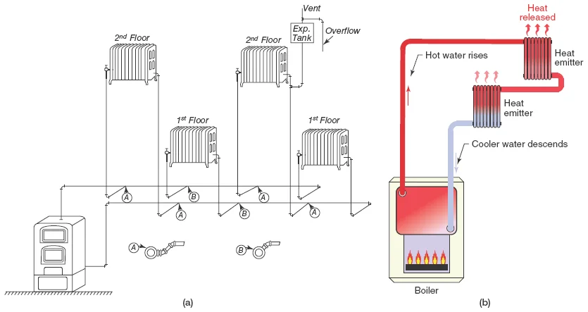
Figure 1 (a) An early (1930s vintage) hydronic heating system without a circulator. (b) Flow occurs due to differences in density between hot water and cooler water.
These early hydronic heating systems required careful pipe sizing and installation since buoyancy-driven flows are weak, and their designs were significantly limited in comparison to what can be done with modern methods. The emergence of electrically powered circulators made it possible to move water at higher flow rates through much more elaborate piping systems.
Modern hydronics technology enables heat to be delivered precisely when and where it is needed. Hundreds of system configurations are possible, each capable of meeting the exact comfort requirements of its owner.
Some may be as simple as a boiler serving a single piping circuit through several series-connected heat emitters. Others may use two or more hydronic heat sources operated in stages, releasing their heat through a wide assortment of heat emitters. Those same heat sources could also provide the building’s domestic hot water. They might even heat the swimming pool or melt snow as it falls on the driveway.
If the heat source is a reversible heat pump, it could also supply chilled water for cooling. Well-designed and properly installed hydronic systems provide unparalleled versatility, unsurpassed comfort, and fuel efficiency for the life of the building.
Benefits of Hydronic Heating
This section discusses several benefits of hydronic heating. Among these are
- Comfort
- Energy savings
- Design flexibility
- Clean operation
- Quiet operation
- Noninvasive installation
- High distribution efficiency
Comfort
Contrary to common belief, heating systems are not created to heat buildings. Instead, they are created for sustaining human thermal comfort within buildings. Think about it: Does a window, concrete block, or insulation batt really “care” whether its temperature is 40 or 70 oF ? Of course not. However, the selection and placement of these materials can have a profound impact on human thermal comfort, or lack thereof.
Providing comfort should be the primary objective of any heating system designer or installer. Unfortunately, this objective is too often compromised by other factors, the most common of which is cost. Even small residential heating systems affect the health, productivity, and general well-being of several people for many years. It makes sense to plan and install them accordingly.
The average North American building owner spends little time thinking about the consequences of the heating system they select. Many view such systems as a necessary but uninteresting part of a building. When construction budgets are tightened, it is often the heating system that is compromised to save money for other, more impressive amenities.
Heating professionals should take the time to discuss the full range of benefits of hydronic systems, including superior comfort, as well as price with their clients. Often people who have lived with uncomfortable heating systems do not realize what they have been missing. In retrospect, many would welcome the opportunity to live or work in truly comfortable buildings and would willingly spend more money, if necessary, to do so.
Maintaining comfort is not a matter of supplying heat to the body. Instead, it is a matter of controlling how the body loses heat. When interior conditions allow heat to leave a person’s body at the same rate at which it is generated, that person feels comfortable. If heat is released faster or slower than the rate at which it is produced, some degree of discomfort is experienced.
A normal adult engaged in light activity generates heat at a rate of approximately 400 British thermal units per hour (Btu/hr). Figure 2 shows the various processes by which the body of a person at rest releases heat to a typical indoor environment.
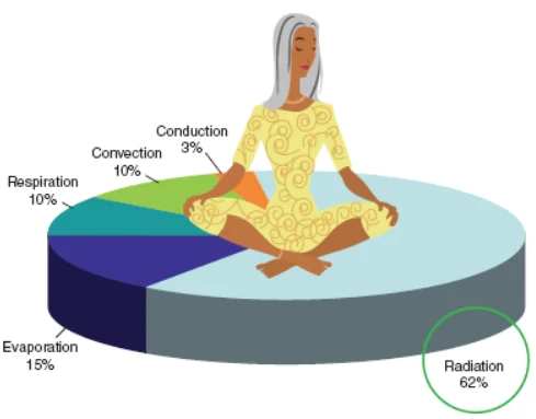
Figure 2 Processes the body uses to release heat to a typical indoor environment.
Notice that a large percentage of the body’s heat loss comes from thermal radiation to surrounding surfaces. Most people will not be comfortable in a room containing several cool surfaces such as large windows or cold floors, even if the room’s air temperature is 70 oF. Remaining heat loss occurs through a combination of convection, evaporation, respiration, and a small amount of conduction. The latter occurs through surfaces in direct contact with the body.
The body can adjust these heat loss processes, within certain ranges, to adapt to different interior environments. For example, if air temperature around the body increases, convection heat loss will be suppressed. The body responds by increasing evaporation heat loss (perspiration) and increasing skin temperature to increase radiative heat loss.
Properly designed hydronic systems control both the air temperature and surface temperatures of rooms to maintain optimal comfort. Modern controls can maintain room air temperature to within ±1 oF of the desired setpoint temperature. Heat emitters such as radiant floors or radiant ceilings raise the average surface temperature of rooms. Since the human body is especially responsive to radiant heat loss, these heat emitters significantly enhance comfort. Comfortable humidity levels are also easier to maintain in hydronically heated buildings.
Several factors such as activity level, age, and general health determine the comfortable environment for a given individual. When several people are living or working in a common environment, any one of them might feel too hot, too cold, or just right. Heating systems that allow various “zones” of a building to be maintained at different temperatures can better adapt to the comfort needs of several individuals. This is called zoning. Although both forced-air and hydronic heating systems can be zoned, the latter is usually much simpler and easier to control.
Energy Savings
Ideally, a building’s rate of heat loss would not be affected by how that heat is replaced. However, experience has shown that otherwise identical buildings can have significantly different rates of heat loss based on the types of heating systems installed. Buildings with hydronic heating systems have consistently shown lower heating energy use than equivalent structures with forced-air heating systems.
A number of factors contribute to this finding. One is that hydronic systems do not adversely affect room air pressure while operating. Small changes in room air pressure occur when the blower of a ducted forced-air heating system is operating. Increased room air pressure is often created by a lack of adequate return air flow from the rooms back to the furnace or air handler. This condition drives heated air out through every small crack, hole, or other opening in the exterior surfaces of the room.
One study that compared several hundred homes, some with central forced-air systems and others with hydronic baseboard convectors, found that air leakage rates averaged 26% higher and energy usage averaged 40% greater in homes with forced-air heating.
Another factor affecting building energy use is air temperature stratification (e.g., the tendency of warm air to rise toward the ceiling while cool air settles to the floor). In extreme situations, the difference in air temperature from floor to ceiling can exceed 20 oF.
Stratification tends to be worsened by high ceilings, poor air circulation, and heating systems that supply air into rooms at high temperatures. Maintaining comfortable air temperatures in the occupied areas of rooms plagued with a high degree of temperature stratification leads to significantly higher air temperatures near the ceiling as shown in Figure 3. This, in turn, increases heat loss through the ceiling.
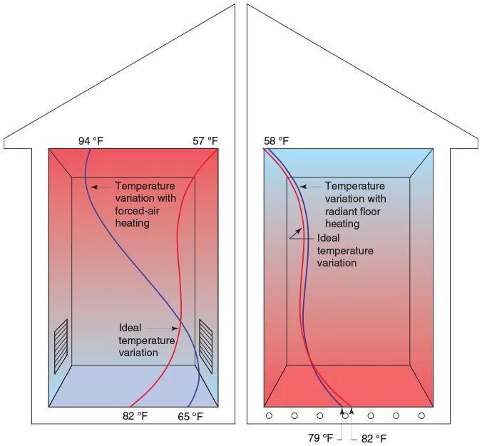
Figure 3 Comparison of air temperatures from floor to ceiling for forced-air heating (left) and radiant floor heating (right).
Hydronic systems that transfer the majority of their heat by thermal radiation reduce air temperature stratification and thus reduce heat loss through ceilings. Comfort can often be maintained at lower air temperatures when a space is radiantly heated. This leads to further energy savings.
Zoned hydronic systems provide the potential for unoccupied rooms to be kept at lower temperatures, which lowers heat loss and reduces fuel consumption. Some hydronic systems also automatically reduce the water temperature in their distribution piping as the outdoor temperature increases. This reduces heat loss from piping routed through unheated or semi-heated spaces.
The electrical energy consumption of the circulator(s) used in a well-planned modern hydronic system can be a small fraction (often less than 10%) of the electrical energy required by a blower in a forced air heating system of equal capacity. This saving is often overlooked by those who only consider the energy use associated with producing heat or chilled water for cooling. This difference in energy use by various heating or cooling distribution systems can be quantified using the concept of distribution efficiency, which is discussed later in this chapter.
Design Flexibility
Modern hydronics technology offers virtually unlimited potential to accommodate the comfort needs, usage, aesthetic tastes, and budget constraints of almost any building. A single system can be designed to supply space heating, domestic hot water, and specialty loads such as pool heating or snowmelting (see Figure 4). Such “multiload” systems reduce installation costs because redundant components such as multiple heat sources, exhaust systems, electrical hookups, safety devices, and fuel supply components are eliminated. They also tend to improve the heat source efficiency and thus reduce fuel usage relative to systems where each load is served by its own dedicated heat source.
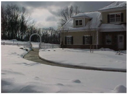
Figure 4 The hydronic system that heats this house also melts snow on the walkway.
The space heating needs of some buildings are best served through the use of different heat emitters. For example, it is possible for hydronic radiant heating to be used in the basement and first floor of a house while the second-floor rooms are heated using panel radiators or fin-tube baseboard. Modern hydronics technology makes it easy to combine different heat emitters into the same system.
The wide variety of hydronic heat sources now available also allows systems to easily adapt to special circumstances or opportunities such as “time-of-use” electrical rates, on-site renewable energy availability, or waste heat recovery.
Clean Operation
A common complaint about forced-air heating is its propensity to move dust and other airborne particles such as pollen and smoke throughout a building. In buildings where air-filtering equipment is either of low quality or is poorly maintained, dust streaks around ceiling diffusers, as seen in Figure 4a, are often evident. Eventually duct systems, such as that shown in Figure 5, require internal cleaning to remove dust and dirt that have accumulated over several years of operation.
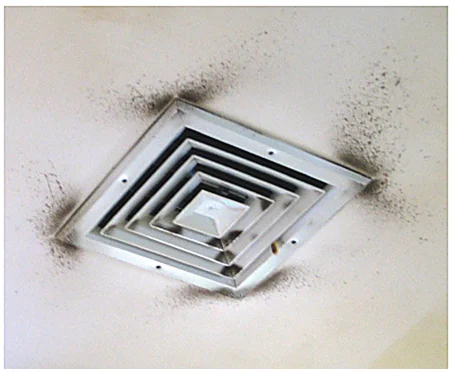
Figure 4a Dust streaks surrounding a ceiling diffuser indicate poor air filtering in a ducted forced-air distribution system.
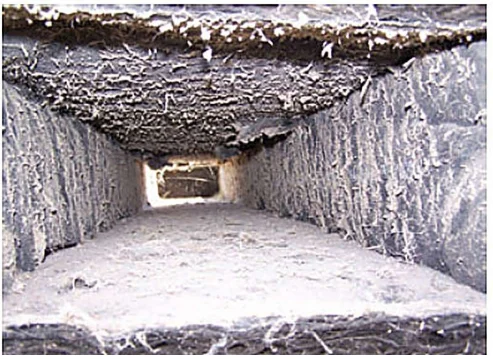
Figure 5 Dirt and dust accumulation in ducting.
In contrast, few hydronic systems involve forced-air circulation. Those that do create room air circulation rather than whole building air circulation. This reduces the dispersal of airborne particles and microorganisms, which is a major benefit in situations where air cleanliness is imperative, such as for people with allergies or respiratory illness, or in health care facilities and laboratories. When floor heating is used in entry areas, the floor can dry rapidly to reduce tracking water and dirt further into the building.
Quiet Operation
Most people want their home to be a quiet refuge from the pace and noise of modern life. They don’t want to hear sounds emanating from their heating and cooling systems. A properly designed and installed hydronic system can operate with virtually no detectable sound levels in the occupied areas of a home. Modern systems that use constant circulation and variable water temperature control minimize expansion noises that can occur when high-temperature water is injected directly into a room temperature heat emitter. These characteristics make hydronic heating ideal in sound-sensitive areas such as home theaters, reading rooms, or recording studios.
Noninvasive Installation
Consider the difficulty encountered when ducts have to be concealed from sight within a typical house. The best that can be done in many situations is to encase the ducting in exposed soffits, as shown in Figure 5a. Such situations often lead to compromises in duct sizing and/or placement.
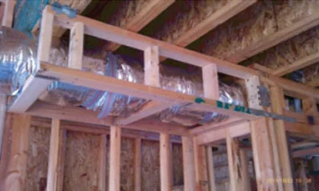
Figure 5a Ducting enclosed in a framed soffit within living space.
By comparison, hydronic heating systems are easily integrated into the structure of most small buildings without compromising their structure or the aesthetic character of the space. The underlying reason for this is the high heat capacity of water. A given volume of water can absorb over 3400 times more heat as the same volume of air for the same temperature change. The volume of water that must be moved through a building to deliver a certain amount of heat is only about 0.03% that of air! This greatly reduces the size of the distribution “conduit.”
For example, a 3/4-inch-diameter tube carrying water at 6.0 gpm around a hydronic system operating with a 20 oF temperature drop transports as much heat as a 14-inch by 8-inch duct carrying 130 oF air at 1000 feet/min. Figure 7 depicts these two options side by side.

Figure 6 Hydronic systems operate with virtually no noise in occupied space.
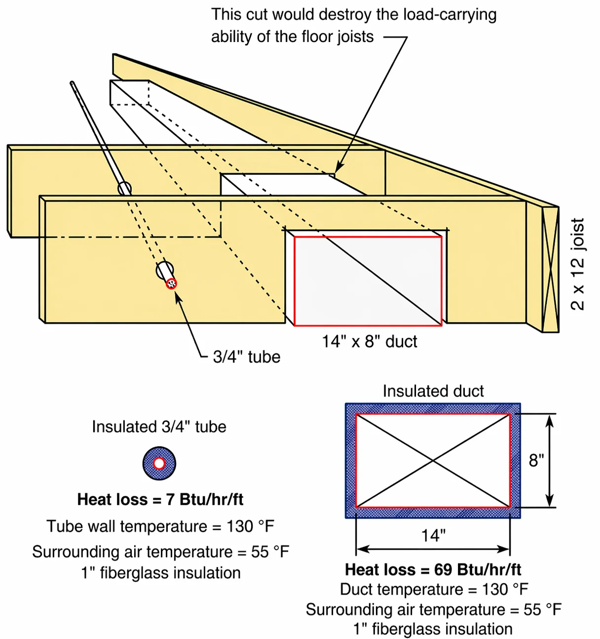
Figure 7 A 3/4-inch-diameter tube carrying water can transport heat at the same rate as a 14-inch by 8-inch duct in a forced-air system. If the water in the tube and air in the duct are of the same temperature, there is almost 10 times more heat loss from the duct due to its larger surface area.
Notching into floor joists to accommodate the 14-inch by 8-inch duct would destroy their structural integrity. By contrast, smaller tubing is easily routed through the framing, especially if it happens to be one of several flexible tube products now available.
If the distribution system is insulated, which is now a code requirement in many areas, considerably less material is required to insulate the tubing compared to the ducting. When insulated with the same material, the heat loss of the 14-inch by 8-inch duct is almost 10 times greater than that of the 3/4-inch tube.
Hydronic systems using small flexible tubing are much easier to retrofit into existing buildings in comparison to ducting. The tubing can be routed through open or closed framing cavities much like electrical cable, as seen in Figure 8.
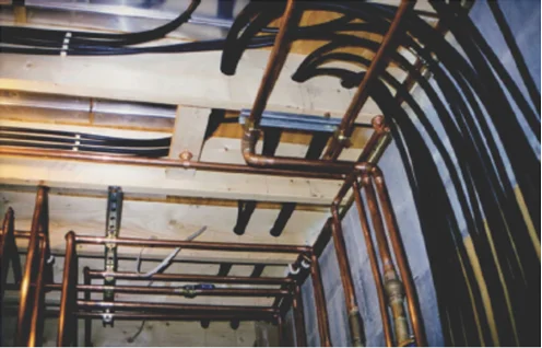
Figure 8 Small-diameter flexible hydronic tubing routed through framing cavities.
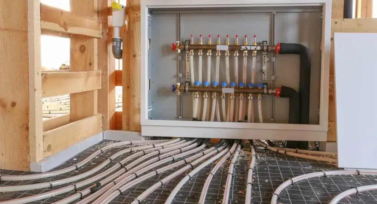
One modern strategy is to route 3/8-inch or 1/2-inch flexible tubing from a central manifold station to a heat emitter in each room. This “homerun” approach allows the option of maintaining different temperatures in each room. The concept is shown in Figure 9.
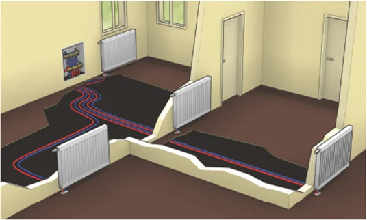
Figure 9 A homerun distribution system uses supply and return tubing from each heat emitter to a central manifold station.
For buildings where utility space is minimal, small wall hung boilers using sealed combustion systems can often be mounted in a closet. In many cases, these compact boilers supply the building’s domestic hot water as well as its heat. The entire system might occupy less than 10 square feet of floor area.
Distribution Efficiency
The electrical power required to move heat or cooling effect through a building is an important consideration when trying to reduce a building’s overall energy use. It’s possible to compare the relative electrical energy use of various heating and cooling distribution systems using the concept of distribution efficiency, which is defined by Equation 1.
$$\begin{matrix} \eta _{d}=\frac{q}{p_{e}} & (1) \end{matrix}$$
Where:
$\eta _{d}=\textrm{distribution efficiency (Btu/hr/watt)}$
$q=\textrm{rate of thermal energy delivered by distribution system (Btu/hr)}$
$p_{e}=\textrm{electrical power required to operate distribution system (watt)}$
Example 1
A hydronic heating distribution system has 3 circulators, each requiring 45 watts of electrical power input when operating at peak capacity. Under this condition the distribution system delivers 160,000 Btu/hr of thermal energy to the building. Determine the distribution efficiency of this system.
Solution
Since both the rate of thermal energy delivery and the associated electrical power input to the distribution system are known, the distribution efficiency is easily calculated.
$$\eta _{d}=\frac{q}{p_{e}}=\frac{\textrm{160,000 Btu/hr}}{3\times \textrm{45 Watts}}=1,185 \frac{Btu/hr}{watt}$$
The calculated value of 1,185 Btu/hr/watt can be interpreted as follow: This hydronic distribution system delivers 1,185 Btu/hr of heat from where it is produced to where it’s needed in the building for each watt of electrical power required to operate the distribution system. Still, the value of 1,185 Btu/hr/watt is somewhat meaningless without something to compare it to. This will be done in example 2.
Example 2
A ducted forced-air heating system uses a blower to deliver 84,000 Btu/h to a building. The blower requires 740 watts of electrical power input when operating. What is the distribution efficiency of this system?
Solution
Again the calculation is straightforward:
$$\eta _{d}=\frac{q}{p_{e}}=\frac{\textrm{84,000 Btu/hr}}{\textrm{740 Watts}}=113.5 \frac{Btu/hr}{watt}$$
In this case the distribution system only delivers 113.5 Btu/hr to where it’s needed in the building for each watt of electrical power required to operate the distribution system. A ratio of the distribution efficiencies calculated in these two examples is 1185/113.5 = 10.4. This implies that the hydronic system delivered about 10.4 times as much heat per watt of electrical power input compared to the forced air system. It could also be interpreted as the hydronic system delivering a given amount of heat using about 9.6 percent, of the electrical power required by the forced air system.
In either case the hydronic distribution system described in example 1 holds a clear advantage over the ducted forced-air distribution system described in example 2. That advantage could result in thousands of dollars of electrical energy savings over the life of these heating systems. Bear in mind that this comparison was for two specific systems, and that the results should not be generalized to all hydronic versus ducted forced-air system comparisons.
Using state-of-the-art design techniques and modern hardware, it is possible to construct hydronic systems having distribution efficiencies over 3,000 Btu/hr/watt. This distinct benefit of properly designed modern hydronic systems has the potential to significantly reduce electrical energy use in a wide range of buildings using all types of hydronic heating and cooling sources.