HVAC design relies heavily on accurate calculations to ensure systems operate efficiently, maintain comfort, and meet performance requirements. From determining heating and cooling loads to sizing equipment and distribution systems, engineers and technicians depend on a wide range of formulas to make informed design decisions. This guide brings together essential HVAC equations used across airside and waterside systems, helping professionals better understand how airflow, temperature differences, and energy transfer interact within a building.
The article covers fundamental relationships such as sensible, latent, and total heat calculations, along with air change rates, fluid flow equations, and psychrometric principles. It also explores critical concepts like fan and pump laws, duct and pipe sizing, energy efficiency metrics, and heat transfer through building envelopes. By presenting both English and metric formulations, the guide supports a wide range of applications and design standards used globally.
In addition to core system calculations, this resource extends into specialized areas such as steam and condensate systems, humidification, cooling towers, and refrigeration-related ventilation. Whether you are performing load calculations, analyzing system performance, or designing complete HVAC systems, these equations serve as a practical reference to support accurate, efficient, and reliable engineering work.
Airside System Equations
$$\text{Sensible Heat} = H_S = 1.08 \times \text{CFM} \times \Delta T$$
$$\text{Latent Heat} = H_L = 0.68 \times \text{CFM} \times \Delta \text{WGR}$$
$$\text{Total Heat} = H_T = 4.5 \times \text{CFM} \times \Delta h$$
$$\mathrm{SHR} = \frac{H_s}{H_T} = \frac{H_s}{H_s + H_L}$$
|
HS |
= sensible heat (Btu/h) |
|
HL |
= latent heat (Btu/h) |
|
HT |
= total heat (Btu/h) |
|
ΔT |
= temperature difference (°F) |
|
ΔWGR. |
= humidity ratio difference (Gr.H2O/lbs.DA) |
|
ΔWLB. |
= humidity ratio difference (lbs.H2O/lbs.DA) |
|
Δh |
= enthalpy difference (Btu/lbs.DA) |
|
CFM |
= air flow rate (cubic feet per minute) |
|
SHR |
= sensible heat ratio |
|
m |
= mass flow (lbs.DA/h) |
|
ca |
= specific heat of air (0.24 Btu/lbs.DA °F) |
|
DA |
= dry air |
Waterside System Equations
$$\text{Total Heat}=H = 500 \times \text{GPM} \times \Delta T$$
$$\text{Evaporator Water Flow Rate= } \text{ GPM}_{\text{EVAP}} = \frac{\text{TONS} \times 24}{\Delta T}$$
$$\text{Condenser Water Flow Rate} = \text{GPM}_{\text{COND}} = \frac{\text{TONS} \times 30}{\Delta T}$$
|
H |
= total heat (Btu/h) |
|
GPM |
= water flow rate (gallons per minute) |
|
ΔT |
= temperature difference (°F) |
|
TONS |
= air conditioning load (tons) |
|
GPMEVAP. |
= evaporator water flow rate (gallons per minute) |
|
GPMCOND. |
= condenser water flow rate (gallons per minute) |
|
cw |
= specific heat of water (1.0 Btu/lbs.H2O) |
Air Change Rate Equations
$$\text{Air Change Rate Per hour} = \frac{\text{CFM} \times 60}{\text{VOLUME}}$$
$$\text{Air Flow Rate} = \text{CFM} = \frac{\text{AC}}{\text{HR}} \times \frac{\text{VOLUME}}{60}$$
|
AC/H |
= air change rate per hour |
|
CFM |
= air flow rate (cubic feet per minute) |
|
VOLUME |
= space volume (cubic feet) |
English/Metric Airside System Equations Comparison
Sensible Heat Equations
$$\text{Sensible Heat (Btu/h)} = H_s = 1.08\,\frac{\text{Btu}\cdot\text{min}}{\text{Hr}\cdot\text{ft}^3\cdot{}^\circ\text{F}} \times \text{CFM} \times \Delta T$$
$$\text{Sensible Heat (kJ/h)} = H_{SM} = 72.42\,\frac{\text{kJ}\cdot\text{min}}{\text{Hr}\cdot\text{m}^3\cdot{}^\circ\text{C}} \times \text{CMM} \times \Delta T_M$$
Latent Heat Equations
$$\text{Latent Heat (Btu/h)} = H_L = 0.68\,\frac{\text{Btu}\cdot\text{min}\cdot\text{lb DA}}{\text{Hr}\cdot\text{ft}^3\cdot\text{Gr H}_2\text{O}} \times \text{CFM} \times \Delta W$$
$$\text{Latent Heat (kJ/h)} = H_{LM} = 177{,}734.8\,\frac{\text{kJ}\cdot\text{min}\cdot\text{kg DA}}{\text{Hr}\cdot\text{m}^3\cdot\text{kg H}_2\text{O}} \times \text{CMM} \times \Delta W_M$$
Total Heat Equations
$$\text{Total Heat (Btu/h)} = H_T = 4.5\,\frac{\text{lb}\cdot\text{min}}{\text{Hr}\cdot\text{ft}^3} \times \text{CFM} \times \Delta h$$
$$\text{Total Heat (kJ/h)} = H_{TM} = 72.09\,\frac{\text{kg}\cdot\text{min}}{\text{Hr}\cdot\text{m}^3} \times \text{CMM} \times \Delta h_M$$
$$H_T = H_s + H_L$$
$$H_{TM} = H_{SM} + H_{LM}$$
|
HS |
= sensible heat (Btu/h) |
|
HSM |
= sensible heat (kJ/h) |
|
HL |
= latent heat (Btu/h) |
|
HLM |
= latent heat (kJ/h) |
|
HT |
= total heat (Btu/h) |
|
HTM |
= total heat (kJ/h) |
|
ΔT |
= temperature difference (°F) |
|
ΔTM |
= temperature difference (°C) |
|
ΔW |
= humidity ratio difference (Gr.H2O/lbs.DA) |
|
ΔWM |
= humidity ratio difference (kg.H2O/kg.DA) |
|
Δh |
= enthalpy difference (Btu/lbs.DA) |
|
ΔhM |
= enthalpy difference (kJ/lbs.DA) |
|
CFM |
= air flow rate (cubic feet per minute) |
|
CMM |
= air flow rate (cubic meters per minute) |
English/Metric Waterside System Equation Comparison
$$\text{Total Heat (Btu/h)} = H = 500\,\frac{\text{Btu}\cdot\text{min}}{\text{Hr}\cdot\text{gal}\cdot{}^\circ\text{F}} \times \text{GPM} \times \Delta T$$
$$\text{Total Heat (kJ/h)} = H_M = 250.8\,\frac{\text{kJ}\cdot\text{min}}{\text{Hr}\cdot\text{Liters}\cdot{}^\circ\text{C}} \times \text{LPM} \times \Delta T_M$$
|
H |
= total heat (Btu/h) |
|
HM |
= total heat (kJ/h) |
|
ΔT |
= temperature difference (°F) |
|
ΔTM |
= temperature difference (°C) |
|
GPM |
= water flow rate (gallons per minute) |
|
LPM |
= water flow rate (liters per minute) |
English/Metric Air Change Rate Equation Comparison
$$\text{Air Change Rate per Hour – English} = \frac{AC}{HR} = \frac{\text{CFM} \times 60\,\frac{\text{min}}{\text{h}}}{\text{VOLUME}}$$
$$\text{Air Change Rate per Hour – Metric} = \frac{AC}{HR_M} = \frac{\text{CMM} \times 60\,\frac{\text{min}}{\text{h}}}{\text{VOLUME}_M}$$
|
AC/HR |
= air change rate per hour – English |
|
AC/HRM |
= air change rate per hour – Metric |
|
VOLUME |
= space volume (cubic feet) |
|
VOLUMEM |
= space volume (cubic meters) |
|
CFM |
= air flow rate (cubic feet per minute) |
|
CMM |
= air flow rate (cubic meters per minute) |
English/Metric Temperature and Other Conversions
$$^{o}\textrm{F}=1.8^{o}\textrm{C}+32$$
$$^\circ\mathrm{C} = \frac{^\circ\mathrm{F} - 32}{1.8}$$
|
°F |
= degrees Fahrenheit |
|
°C |
= degrees Celsius |
|
kJ/h |
= Btu/h × 1.055 |
|
CMM |
= CFM × 0.02832 |
|
LPM |
= GPM × 3.785 |
|
kJ/kg |
= Btu/lbs. × 2.326 |
|
meters |
= ft. × 0.3048 |
|
sq. meters |
= sq. ft. × 0.0929 |
|
cu. meters |
= cu. ft. × 0.02832 |
|
kg |
= lbs. × 0.4536 |
|
1.0 GPM |
= 500 lbs. steam/h |
|
1.0 lbs. stm./h |
= 0.002 GPM |
|
1.0 lbs. H2O/h |
= 1.0 lbs. steam/h |
|
kg/cu. meter |
= lbs./cu. ft. × 16.017 (Density) |
|
cu. meters/kg |
= cu. ft./lbs. × 0.0624 (Specific Volume) |
|
kg H2O/kg DA |
= Gr.H2O/lbs.DA/7,000 = lbs.H2O/lbs.DA |
Steam and Condensate Equations
A. General
$$\text{LBS.STM./HR} = \frac{\text{BTU/HR}}{H_{FG}} = \frac{\text{BTU/HR}}{960}$$
$$\text{LBS.STM.COND./HR} = \frac{\text{EDR}}{4}$$
$$\text{Equivalent Direct Radiation} = \text{EDR} = \frac{\text{BTU/HR}}{240}$$
$$\text{LBS.STM.COND./HR} = \frac{\text{GPM} \times 500 \times \text{SP.GR.} \times C_w \times \Delta T}{H_{FG}}$$
$$\text{LBS.STM.COND./HR} = \frac{\text{CFM} \times 60 \times D \times C_a \times \Delta T}{H_{FG}}$$
B. Approximating Condensate Loads
$$\text{LBS.STM.COND./HR} = \frac{\text{GPM (WATER)} \times \Delta T}{2}$$
$$\text{LBS.STM.COND./HR} = \frac{\text{GPM (FUEL OIL)} \times \Delta T}{4}$$
$$\text{LBS.STM.COND./HR} = \frac{\text{CFM (AIR)} \times \Delta T}{900}$$
|
stm. |
= steam |
|
GPM |
= quantity of liquid (gallons per minute) |
|
CFM |
= quantity of gas or air (cubic feet per minute) |
|
SP.GR. |
= specific gravity |
|
D |
= density (lbs./cubic feet) |
|
Ca |
= specific heat of air (0.24 Btu/lbs.) |
|
Cw |
= specific heat of water (1.00 Btu/lbs.) |
|
HFG |
= latent heat of steam (Btu/lbs.) at steam design pressure (ASHRAE Fundamentals) |
|
ΔT |
= final temperature minus initial temperature |
|
EDR |
= equivalent direct radiation |
Building Envelope Heating Equation and R-Values/U-Values
$$\text{Heat Flow} = H = U \times A \times \Delta T$$
$$\text{R-Value} = R = \frac{1}{C} = \frac{1}{K} \times \text{Thickness (in.)}$$
$$R = \frac{1}{\sum R}$$
|
H |
= heat flow (Btu/h) |
|
ΔT |
= temperature difference (°F) |
|
A |
= area (sq.ft.) |
|
U |
= U-Value (Btu./h sq.ft. °F): See Part 35 for definitions. |
|
R |
= R-Value (h sq.ft. °F/Btu.): See Part 35 for definitions. |
|
C |
= conductance (Btu./h sq.ft. °F): See Part 35 for definitions. |
|
K |
= conductivity (Btu. in./h sq.ft. °F): See Part 35 for definitions. |
|
ΣR |
= sum of the individual R-Values |
Fan Laws
$$\frac{\text{CFM}_2}{\text{CFM}_1} = \frac{\text{RPM}_2}{\text{RPM}_1}$$
$$\frac{\text{SP}_2}{\text{SP}_1} = \left(\frac{\text{CFM}_2}{\text{CFM}_1}\right)^2 = \left(\frac{\text{RPM}_2}{\text{RPM}_1}\right)^2$$
$$\frac{\text{BHP}_2}{\text{BHP}_1} = \left(\frac{\text{CFM}_2}{\text{CFM}_1}\right)^3 = \left(\frac{\text{RPM}_2}{\text{RPM}_1}\right)^3 = \left(\frac{\text{SP}_2}{\text{SP}_1}\right)^{1.5}$$
$$\text{BHP} = \frac{\text{CFM} \times \text{SP} \times \text{SP.GR.}}{6356 \times \text{FAN}_{\text{EFF}}}$$
$$\text{MHP} = \frac{\text{BHP}}{\text{M/D}_{\text{EFF}}}$$
|
CFM |
= cubic feet/minute |
|
RPM |
= revolutions/minute |
|
SP |
= static pressure, in. W.G. |
|
BHP |
= brake horsepower |
|
Fan Size |
= constant |
|
Air Density |
= constant |
|
SP.GR.(Air) |
= 1.0 |
|
FANEFF |
= 65–85% |
|
M/DEFF |
= 80–95% |
|
M/D |
= motor/drive |
Pump Laws
$$\frac{\text{GPM}_2}{\text{GPM}_1} = \frac{\text{RPM}_2}{\text{RPM}_1}$$
$$\frac{\text{HD}_2}{\text{HD}_1} = \left(\frac{\text{GPM}_2}{\text{GPM}_1}\right)^2 = \left(\frac{\text{RPM}_2}{\text{RPM}_1}\right)^2$$
$$\frac{\text{BHP}_2}{\text{BHP}_1} = \left(\frac{\text{GPM}_2}{\text{GPM}_1}\right)^3 = \left(\frac{\text{RPM}_2}{\text{RPM}_1}\right)^3 = \left(\frac{\text{HD}_2}{\text{HD}_1}\right)^{1.5}$$
$$\text{BHP} = \frac{\text{GPM} \times \text{HD} \times \text{SP.GR.}}{3960 \times \text{PUMP}_{\text{EFF}}}$$
$$\text{MHP} = \frac{\text{BHP}}{\text{M/D}_{\text{EFF}}}$$
$$\text{VH} = \frac{V^2}{2g}$$
$$\text{HD} = \frac{P \times 2.31}{\text{SP.GR.}}$$
|
GPM |
= gallons/minute |
|
RPM |
= revolutions/minute |
|
HD |
= head in ft. H2O |
|
BHP |
= brake horsepower |
|
Pump Size |
= constant |
|
Water Density |
= constant |
|
SP.GR. |
= specific gravity of liquid with respect to water |
|
SP.GR.(Water) |
= 1.0 |
|
PUMPEFF |
= 60–80% |
|
M/DEFF |
= 85–95% |
|
M/D |
= motor/drive |
|
P |
= pressure (psi) |
|
VH |
= velocity head in ft. H2O |
|
V |
= velocity (ft./sec.) |
|
g |
= acceleration due to gravity (32.16 ft./sec.2) |
Pump Net Positive Suction Head (NPSH) Calculations
$$\text{NPSH}_{\text{AVAIL}} > \text{NPSH}_{\text{REQ'D}}$$
|
NPSHAVAIL |
= HA ± HS – HF – HVP |
|
NPSHAVAIL |
= net positive suction available at pump (feet) |
|
NPSHREQ'D |
= net positive suction required at pump (feet) |
|
HA |
= pressure at liquid surface (feet – 34 feet for water at atmospheric pressure) |
|
HS |
= height of liquid surface above (+) or below (–) pump (feet) |
|
HF |
= friction loss between pump and source (feet) |
|
HVP |
= absolute pressure of water vapor at liquid temperature (feet – ASHRAE Fundamentals) |
|
Note: Calculations may also be performed in psig, provided that all values are in psig. |
|
Mixed Air Temperature
$$T_{MA} = \left(T_{ROOM} \times \frac{\text{CFM}_{RA}}{\text{CFM}_{SA}}\right) + \left(T_{OA} \times \frac{\text{CFM}_{OA}}{\text{CFM}_{SA}}\right)$$
$$T_{MA} = \left(T_{RA} \times \frac{\text{CFM}_{RA}}{\text{CFM}_{SA}}\right) + \left(T_{OA} \times \frac{\text{CFM}_{OA}}{\text{CFM}_{SA}}\right)$$
|
CFMSA |
= supply air CFM |
|
CFMRA |
= return air CFM |
|
CFMOA |
= outside air CFM |
|
TMA |
= mixed air temperature (°F) |
|
TROOM |
= room design temperature (°F) |
|
TRA |
= return air temperature (°F) |
|
TOA |
= outside air temperature (°F) |
Psychrometric Equations
$$W = 0.622 \,\frac{P_w}{P - P_w}$$
$$\text{RH} \cong \frac{W_{\text{ACTUAL}}}{W_{\text{SAT}}} \times 100\%$$
$$\text{RH} = \frac{P_w}{P_{\text{SAT}}} \times 100\%$$
$$H_s = m \times c_p \times \Delta T$$
$$H_L = L_v \times m \times \Delta W$$
$$H_T = m \times \Delta h$$
$$W = \frac{(2501 - 2.381\,T_{WB})\,(W_{SAT\,WB}) - (T_{DB} - T_{WB})}{(2501 + 1.805\,T_{DB} - 4.186\,T_{WB})}$$
$$W = \frac{(1093 - 0.556\,T_{WB})\,(W_{SAT\,WB}) - 0.240\,(T_{DB} - T_{WB})}{(1093 + 0.444\,T_{DB} - T_{WB})}$$
|
W |
= specific humidity, lbs.H2O/lbs.DA or Gr.H2O/lbs.DA |
|
WACTUAL |
= actual specific humidity, lbs.H2O/lbs.DA or Gr.H2O/lbs.DA |
|
WSAT |
= saturation specific humidity at the dry bulb temperature |
|
WSAT WB |
= saturation specific humidity at the wet bulb temperature |
|
PW |
= partial pressure of water vapor, lbs./sq.ft. |
|
P |
= total absolute pressure of air/water vapor mixture, lbs./sq.ft. |
|
PSAT |
= saturation partial pressure of water vapor at the dry bulb temperature, lbs./sq.ft. |
|
RH |
= relative humidity, % |
|
HS |
= sensible heat, Btu/h |
|
HL |
= latent heat, Btu/h |
|
HT |
= total heat, Btu/h |
|
m |
= mass flow rate, lbs.DA/h or lbs.H2O/h |
|
cP |
= specific heat, Air—0.24 Btu/lbs.DA, Water—1.0 Btu/lbs.H2O |
|
TDB |
= dry bulb temperature, °F |
|
TWB |
= wet bulb temperature, °F |
|
ΔT |
= temperature difference, °F |
|
ΔW |
= specific humidity difference, lbs.H2O/lbs.DA or Gr.H2O/lbs.DA |
|
Δh |
= enthalpy difference, Btu/lbs.DA |
|
LV |
= latent heat of vaporization, Btu/lbs.H2O |
Ductwork Equations
$$TP = SP + VP$$
$$VP = \left(\frac{V}{4005}\right)^2 = \frac{V^2}{(4005)^2}$$
$$V = \frac{Q}{A} = \frac{Q \times 144}{W \times H}$$
$$D_{EQ} = \frac{1.3 \times (A \times B)^{0.625}}{(A + B)^{0.25}}$$
|
TP |
= total pressure |
|
SP |
= static pressure, friction losses |
|
VP |
= velocity pressure, dynamic losses |
|
V |
= velocity, ft./min. |
|
Q |
= air flow rate through duct, CFM |
|
A |
= area of duct, sq.ft. |
|
W |
= width of duct, in. |
|
H |
= height of duct, in. |
|
DEQ |
= equivalent round duct size for rectangular duct, in. |
|
A |
= one dimension of rectangular duct, in. |
|
B |
= adjacent side of rectangular duct, in. |
Equations for Flat Oval Ductwork
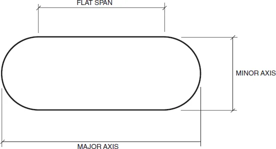
$$FS = \text{MAJOR} - \text{MINOR}$$
$$A = \frac{(FS \times \text{MINOR}) + \frac{\pi \times \text{MINOR}^2}{4}}{144}$$
$$P = \frac{(\pi \times \text{MINOR}) + (2 \times FS)}{12}$$
$$D_{EQ} = \frac{1.55 \times A^{0.625}}{P^{0.25}}$$
|
FS |
= flat span dimension in inches |
|
MAJOR |
= major axis dimension in inches (larger dimension) |
|
MINOR |
= minor axis dimension in inches (smaller dimension) |
|
A |
= cross-sectional area in square feet |
|
P |
= perimeter or surface area in square feet per lineal feet |
|
DEQ |
= equivalent round duct diameter |
Steel Pipe Equations
|
A |
= 0.785 × ID2 |
|
WP |
= 10.6802 × T × (OD – T) |
|
WW |
= 0.3405 × ID2 |
|
OSA |
= 0.2618 × OD |
|
ISA |
= 0.2618 × ID |
|
AM |
= 0.785 × (OD2 – ID2) |
|
A |
= cross sectional area (sq.in.) |
|
WP |
= weight of pipe per foot (lbs.) |
|
WW |
= weight of water per foot (lbs.) |
|
T |
= pipe wall thickness (in.) |
|
ID |
= inside diameter (in.) |
|
OD |
= outside diameter (in.) |
|
OSA |
= outside surface area per foot (sq.ft.) |
|
ISA |
= inside surface area per foot (sq.ft.) |
|
AM |
= area of the metal (sq.in.) |
Steam and Steam Condensate Pipe Sizing Equations
A. Steam Pipe Sizing Equations
$$\Delta P = \frac{0.01306 \times W^2 \left(1 + \frac{3.6}{ID}\right)}{3600 \times D \times ID^5}$$
$$W = 60 \times \sqrt{\frac{\Delta P \times D \times ID^5}{0.01306 \times \left(1 + \frac{3.6}{ID}\right)}}$$
$$W = 0.41667 \times V \times A_{\text{INCHES}} \times D = 60 \times V \times A_{\text{FEET}} \times D$$
$$V = \frac{2.4 \times W}{A_{\text{INCHES}} \times D} = \frac{W}{60 \times A_{\text{FEET}} \times D}$$
|
ΔP |
= pressure drop per 100 ft. of pipe, psig/100 ft. |
|
W |
= steam flow rate, lbs./h |
|
ID |
= actual inside diameter of pipe, in. |
|
D |
= average density of steam at system pressure, lbs./cu.ft. |
|
V |
= velocity of steam in pipe, ft./min. |
|
AINCHES |
= actual cross-sectional area of pipe, sq.in. |
|
AFEET |
= actual cross-sectional area of pipe, sq.ft. |
B. Steam Condensate Pipe Sizing Equations
$$FS = \frac{H_{S(SS)} - H_{S(CR)}}{H_{L(CR)}} \times 100$$
$$W_{CR} = \frac{FS}{100} \times W$$
|
FS |
= flash steam, percentage % |
|
HSSS |
= sensible heat at steam supply pressure, Btu/lbs. |
|
HSCR |
= sensible heat at condensate return pressure, Btu/lbs. |
|
HLCR |
= latent heat at condensate return pressure, Btu/lbs. |
|
W |
= steam flow rate, lbs./h |
|
WCR |
= condensate flow based on percentage of flash steam created during condensing process, lbs./h. Use this flow rate in the preceding steam equations to determine the condensate return pipe size. |
Air Conditioning Condensate
$$\text{GPM}_{AC\,COND} = \frac{\text{CFM} \times \Delta W_{\text{LB}}}{SpV \times 8.33}$$
$$\text{GPM}_{AC\,COND} = \frac{\text{CFM} \times \Delta W_{\text{GR}}}{SpV \times 8.33 \times 7000}$$
|
GPMAC COND |
= air conditioning condensate flow (gal./min.) |
|
CFM |
= air flow rate (cu.ft./min.) |
|
SpV |
= specific volume of air (cu.ft./lbs.DA) = 13.33 ft3/lbs. DA at 60°F |
|
ΔWLB. |
= specific humidity (lbs.H2O/lbs.DA) |
|
ΔWGR. |
= specific humidity (Gr.H2O/lbs.DA) |
Humidification
$$\text{GRAINS}_{\text{REQ'D}} = \left(\frac{W_{\text{GR}}}{SpV}\right)_{\text{ROOM AIR}} - \left(\frac{W_{\text{GR}}}{SpV}\right)_{\text{SUPPLY AIR}}$$
$$\text{POUNDS}_{\text{REQ'D}} = \left(\frac{W_{\text{LB}}}{SpV}\right)_{\text{ROOM AIR}} - \left(\frac{W_{\text{LB}}}{SpV}\right)_{\text{SUPPLY AIR}}$$
$$\text{LBS.STM./HR} = \frac{\text{CFM} \times \text{GRAINS}_{\text{REQ'D}} \times 60}{7000} = \text{CFM} \times \text{POUNDS}_{\text{REQ'D}} \times 60$$
|
GRAINSREQ'D |
= grains of moisture required (Gr.H2O/cu.ft.) |
|
POUNDSREQ'D |
= pounds of moisture required (lbs.H2O/cu.ft.) |
|
CFM |
= air flow rate (cu.ft./min.) |
|
SpV |
= specific volume of air (cu.ft./lbs.DA) |
|
WGR. |
= specific humidity (Gr.H2O/lbs.DA) |
|
WLB. |
= specific humidity (lbs.H2O/lbs.DA) |
Humidifier Sensible Heat Gain
$$H_s = (0.244 \times Q \times \Delta T) + (L \times 380)$$
|
HS |
= sensible heat gain (Btu/h) |
|
Q |
= steam flow (lbs. steam/h) |
|
ΔT |
= steam temperature – supply air temperature (°F) |
|
L |
= length of humidifier manifold (ft.) |
Expansion Tanks
$$\text{CLOSED } V_T = V_s \times \frac{\left[\left(\frac{v_2}{v_1}\right) - 1\right] - 3\alpha \Delta T}{\left(\frac{P_A}{P_1} - \frac{P_A}{P_2}\right)}$$
$$\text{OPEN } V_T = 2 \left\{ V_s \left[ \left(\frac{v_2}{v_1}\right) - 1 \right] - 3\alpha \Delta T \right\}$$
$$\text{DIAPHRAGM } V_T = V_s\times \frac{\left[ \left(\frac{v_2}{v_1}\right) - 1 \right] - 3\alpha \Delta T}{1 - \left(\frac{P_1}{P_2}\right)}$$
|
VT |
= volume of expansion tank (gallons) |
|
|
VS |
= volume of water in piping system (gallons) |
|
|
ΔT |
= T2 – T1 (°F) |
|
|
T1 |
= lower system temperature (°F) |
|
|
Heating Water |
T1 = 45–50°F temperature at fill condition |
|
|
Chilled Water |
T1 = supply water temperature |
|
|
Dual Temperature |
T1 = chilled water supply temperature |
|
|
T2 |
= higher system temperature (°F) |
|
|
Heating Water |
T2 = supply water temperature |
|
|
Chilled Water |
T2 = 95°F ambient temperature (design weather data) |
|
|
Dual Temperature |
T2 = heating water supply temperature |
|
|
PA |
= atmospheric pressure (14.7 psia) |
|
|
P1 |
= system fill pressure/minimum system pressure (psia) |
|
|
P2 |
= system operating pressure/maximum operating pressure (psia) |
|
|
v1 |
= SpV of H2O at T1 (cu.ft./lbs.H2O) ASHRAE Fundamentals |
|
|
v2 |
= SpV of H2O at T2 (cu.ft./lbs.H2O) ASHRAE Fundamentals |
|
|
α |
= linear coefficient of expansion |
|
|
αSTEE = 6.5 × 10⁻⁶ |
||
|
αCOPPER = 9.5 × 10⁻⁶ |
||
|
System Volume Estimate: |
||
|
12 gal./ton |
||
|
35 gal./BHP |
||
|
System Fill Pressure/Minimum System Pressure Estimate: |
||
|
Height of System + 5 to 10 psi OR 5–10 psi, whichever is greater. |
||
|
System Operating Pressure/Maximum Operating Pressure Estimate: |
||
|
150 lbs. Systems |
45–125 psi |
|
|
250 lbs. Systems |
125–225 psi |
|
Air Balance Equations
|
SA |
= Supply Air |
|
RA |
= Return Air |
|
OA |
= Outside Air |
|
EA |
= Exhaust Air |
|
RFA |
= Relief Air |
|
SA |
= RA + OA = RA + EA + RFA |
|
If minimum OA (ventilation air) is greater than EA, then |
|
|
OA = EA + RFA |
|
|
If EA is greater than minimum OA (ventilation air), then |
|
|
OA = EA |
RFA = 0 |
|
For Economizer Cycle: |
|
|
OA = SA = EA + RFA |
RA = 0 |
Efficiencies
$$\text{COP} = \frac{\text{BTU OUTPUT}}{\text{BTU INPUT}} = \frac{\text{EER}}{3.413}$$
$$\text{EER} = \frac{\text{BTU OUTPUT}}{\text{WATTS INPUT}} = \text{COP} \times 3.413$$
$$\text{kW/TON} = \frac{12{,}000\ \text{BTU/HR TON}}{\text{COP} \times 3{,}517\ \text{BTU/HR kW}}$$
$$\text{Turndown Ratio} = \text{Maximum Firing Rate} : \text{Minimum Firing Rate}$$
$$\text{OVERALL THERMAL EFF.} = \frac{\text{GROSS BTU OUTPUT}}{\text{GROSS BTU INPUT}} \times 100\%$$
$$\text{COMBUSTION EFF.} = \frac{\text{BTU INPUT} - \text{BTU STACK LOSS}}{\text{BTU INPUT}} \times 100\%$$
$$\text{Overall Thermal Efficiency Range} = 75\% - 90\%$$
$$\text{Combustion Efficiency Range} = 85\% - 95\%$$
|
COP |
= coefficient of performance |
|
EER |
= energy efficiency ratio |
Cooling Towers and Heat Exchangers
$$\text{APPROACH}_{\text{CT'S}} = \text{LWT} - \text{AWB}$$
$$\text{APPROACH}_{\text{HE'S}} = \text{EWT}_{HS} - \text{LWT}_{CS}$$
$$\text{RANGE} = \text{EWT} - \text{LWT}$$
|
EWT |
= entering water temperature (°F) |
|
LWT |
= leaving water temperature (°F) |
|
AWB |
= ambient wet bulb temperature (Design WB – °F) |
|
HS |
= hot side |
|
CS |
= cold side |
Cooling Tower/Evaporative Cooler Blowdown Equations
$$C = \frac{E + D + B}{D + B}$$
$$B = \frac{E - \left[(C - 1) \times D\right]}{C - 1}$$
|
E |
= GPMCOND. × R × 0.0008 |
|
D |
= GPMCOND. × 0.0002 |
|
R |
= EWT – LWT |
|
B |
= blowdown, GPM |
|
C |
= cycles of concentration |
|
D |
= drift, GPM |
|
E |
= evaporation, GPM |
|
EWT |
= entering water temperature, °F |
|
LWT |
= leaving water temperature, °F |
|
R |
= range, °F |
|
GPMCOND. |
= condenser water flow rate (gallons per minute) |
Electricity
A. General
|
KVA |
= KW + KVAR |
|
PF |
= KW/KVA |
B. Single-Phase Power
$$\text{kW}_{1\phi} = \frac{V \times A \times PF}{1000}$$
$$\text{kVA}_{1\phi} = \frac{V \times A}{1000}$$
$$\text{BHP}_{1\phi} = \frac{V \times A \times PF \times \text{DEVICE}_{\text{EFF}}}{746}$$
$$\text{MHP}_{1\phi} = \frac{\text{BHP}_{1\phi}}{\text{M/D}_{\text{EFF}}}$$
C. Three-Phase Power
$$\text{kW}_{3\phi} = \frac{\sqrt{3} \times V \times A \times PF}{1000}$$
$$\text{kVA}_{3\phi} = \frac{\sqrt{3} \times V \times A}{1000}$$
$$\text{BHP}_{3\phi} = \frac{\sqrt{3} \times V \times A \times PF \times \text{DEVICE}_{\text{EFF}}}{746}$$
$$\text{MHP}_{3\phi} = \frac{\text{BHP}_{3\phi}}{\text{M/D}_{\text{EFF}}}$$
|
KVA |
= total power (kilovolt amps) |
|
KW |
= real power, electrical energy (kilowatts) |
|
KVAR |
= reactive power or "imaginary" power (kilovolt amps reactive) |
|
V |
= voltage (volts) |
|
A |
= current (amps) |
|
PF |
= power factor (0.75–0.95) |
|
BHP |
= brake horsepower |
|
MHP |
= motor horsepower |
|
EFF |
= efficiency |
|
M/D |
= motor drive |
Moisture Condensation on Glass
$$T_{\text{GLASS}} = T_{\text{ROOM}} - \left[\frac{R_{IA}}{R_{\text{GLASS}}} \times (T_{\text{ROOM}} - T_{OA})\right]$$
$$T_{\text{GLASS}} = T_{\text{ROOM}} - \left[\frac{U_{\text{GLASS}}}{U_{IA}} \times (T_{\text{ROOM}} - T_{OA})\right]$$
$$\text{If } T_{\text{GLASS}} < DP_{\text{ROOM}}, \text{ condensation occurs}$$
|
T |
= temperature (°F) |
|
R |
= R-Value (h sq.ft. °F/Btu) |
|
U |
= U-Value (Btu./h sq.ft. °F) |
|
IA |
= inside airfilm |
|
= design outside air temperature |
|
|
DP |
= dewpoint |
Calculating Heating Loads for Loading Docks, Heavily Used Vestibules and Similar Spaces
- Find volume of space to be heated (cu.ft.).
- Determine acceptable warm-up time for space (min.).
- Divide volume by time (CFM).
- Determine inside and outside design temperatures—assume inside space temperature has dropped to the outside design temperature because doors have been open for an extended period of time.
- Use sensible heat equation to determine heating requirement using CFM and inside and outside design temperatures determined earlier in this Part.
Ventilation of Mechanical Rooms with Refrigeration Equipment
A. For a more detailed description of ventilation requirements for mechanical rooms with refrigeration equipment, see ASHRAE Standard 15 and Part 8.
B. Completely Enclosed Equipment Rooms
|
CFM |
= 100 × G0.5 |
|
CFM |
= exhaust air flow rate required (cu.ft./minute) |
|
G |
= mass of refrigerant of largest system (pounds) |
C. Partially Enclosed Equipment Rooms
|
FA |
= G0.5 |
|
FA |
= ventilation free opening Area (sq.ft.) |
|
G |
= mass of refrigerant of largest system (pounds) |
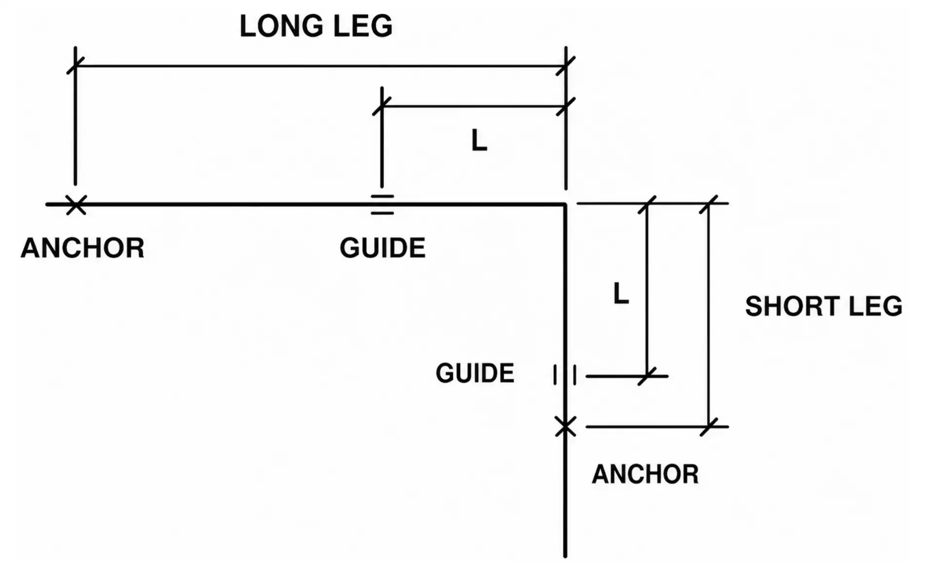
Pipe Expansion Equations
A. L-Bends
|
L |
= 6.225 × $\sqrt{AD}$ |
|
F |
= 500 LB./PIPE DIA. × PIPE DIA. |
|
L |
= length of leg required to accommodate thermal expansion or contraction, feet |
|
Δ |
= thermal expansion or contraction of long leg, inches |
|
D |
= pipe outside diameter, inches |
|
F |
= force exerted by pipe expansion or contraction on anchors and supports, lbs. |
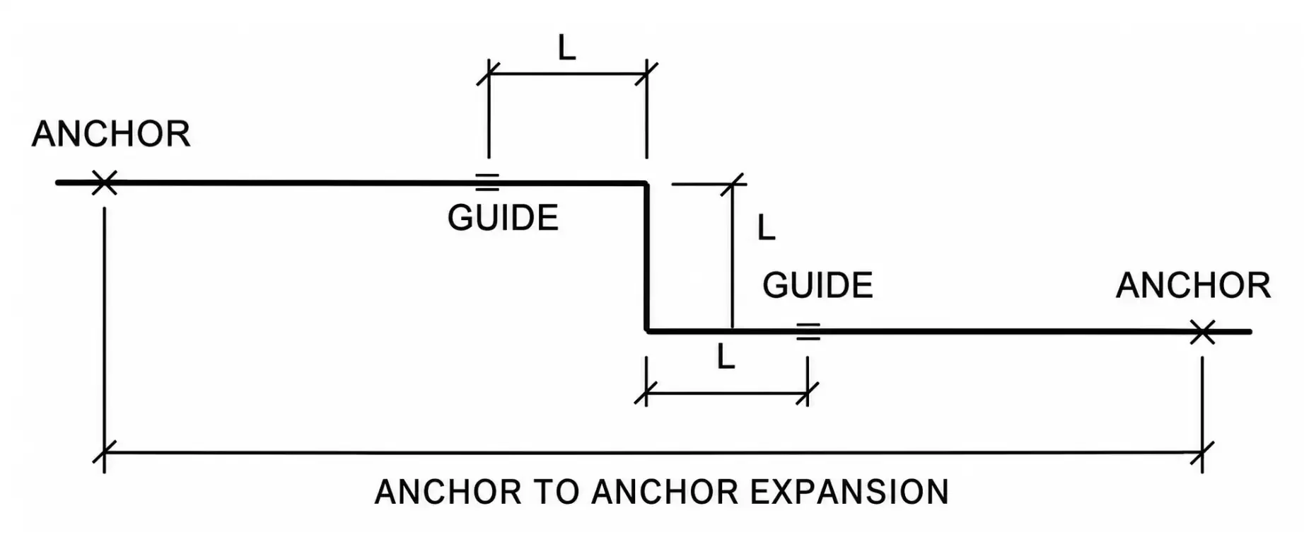
B. Z-Bends
|
L |
= 4 × $\sqrt{AD}$ |
|
F |
= 200 – 500 LB./PIPE DIA. × PIPE DIA. |
|
L |
= length of offset leg required to accommodate thermal expansion or contraction, feet |
|
Δ |
= anchor to anchor expansion or contraction, inches |
|
D |
= pipe outside diameter, inches |
|
F |
= force exerted by pipe expansion or contraction on anchors and supports, lbs. |
C. U-Bends or Expansion Loops
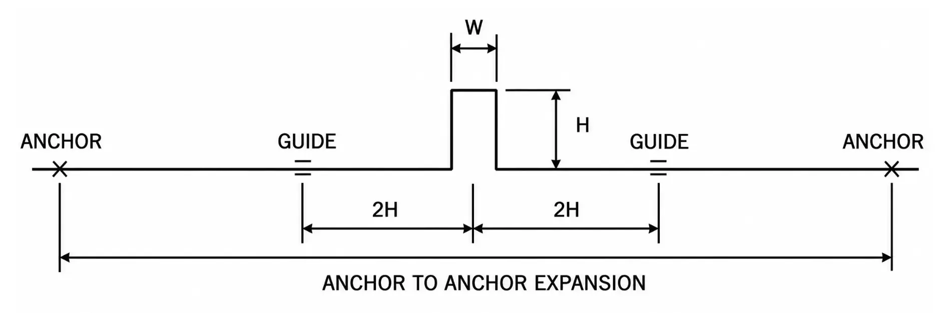
|
L |
= 6.225 × $\sqrt{AD}$ |
|
F |
= 200 LB./PIPE DIA. × PIPE DIA. |
|
L |
= 2H + W |
|
H |
= 2W |
|
L |
= 5W |
|
L |
= length of loop required to accommodate thermal expansion or contraction, ft. |
|
Δ |
= anchor to anchor expansion or contraction, in. |
|
D |
= pipe outside diameter, in. |
|
F |
= force exerted by pipe expansion or contraction on anchors and supports, lbs. |
Relief Valve Vent Line Maximum Length
$$L = \frac{9 \times P_1^2 \times D^5}{C^2} = \frac{9 \times P_2^2 \times D^5}{16 \times C^2}$$
|
P1 |
= 0.25×[(PRESSURE SETTING ×1.1)+14.7] |
|
P2 |
= [(PRESSURE SETTING ×1.1)+14.7] |
|
L |
= maximum length of relief vent line in feet |
|
D |
= inside diameter of pipe in inches |
|
C |
= minimum discharge of air in lbs./min. |
Relief Valve Sizing
A. Liquid System Relief Valves—Spring-Style Relief Valves
$$A = \frac{\text{GPM} \times \sqrt{G}}{28.14 \times K_B \times K_V \times \sqrt{\Delta P}}$$
B. Liquid System Relief Valves—Pilot-Operated Relief Valves
$$A = \frac{\text{GPM} \times \sqrt{G}}{36.81 \times K_V \times \sqrt{\Delta P}}$$
C. Steam System Relief Valves
$$A = \frac{W}{51.5 \times K \times P \times K_{SH} \times K_N \times K_B}$$
D. Gas and Vapor System Relief Valves—lbs./h
$$A = \frac{W \times \sqrt{TZ}}{C \times K \times P \times K_B \times \sqrt{M}}$$
E. Gas and Vapor System Relief Valves—SCFM
$$A = \frac{\text{SCFM} \times \sqrt{TGZ}}{1.175 \times C \times K \times P \times K_B}$$
F. Relief Valve Equation Definitions
|
1. A |
= Minimum required effective relief valve discharge area (sq.in.) |
|
2. GPM |
= Required relieving capacity at flow conditions (gal./min.) |
|
3. W |
= Required relieving capacity at flow conditions (lbs./h) |
|
4. SCFM |
= Required relieving capacity at flow conditions (standard cu.ft./min.) |
|
5. G |
= Specific gravity of liquid, gas, or vapor at flow conditions Water = 1.0 for most HVAC applications Air = 1.0 |
|
6. C |
= Coefficient determined from expression of ratio of specific heats C = 315 if value is unknown |
|
7. K |
= Effective coefficient of discharge K = 0.975 |
|
8. KB |
= Capacity correction factor due to back pressure KB = 1.0 for atmospheric discharge systems |
|
9. KV |
= Flow correction factor due to viscosity KV = 0.9 to 1.0 for most HVAC applications with water |
|
10. KN |
= Capacity correction factor for dry saturated steam at set pressures above 1500 psia and up to 3200 psia KN = 1.0 for most HVAC applications |
|
11. KSH |
= Capacity correction factor due to the degree of superheat KSH = 1.0 for saturated steam |
|
12. Z |
= Compressibility factor Z = 1.0 if value is unknown |
|
13. P |
= Relieving pressure (psia) P = Set pressure (psig) + over pressure (10% psig) + atmospheric pressure (14.7 psia) |
|
14. ΔP |
= Differential pressure (psig) ΔP = Set pressure (psig) + over pressure (10% psig) – back pressure (psig) |
|
15. T |
= Absolute temperature (°R = °F + 460) |
|
16. M |
= Molecular weight of the gas or vapor |
G. Relief Valve Sizing Notes
- When multiple relief valves are used, one valve shall be set at or below the maximum allowable working pressure, and the remaining valves may be set up to 5 percent over the maximum allowable working pressure.
- When sizing multiple relief valves, the total area required is calculated on an over pressure of 16 percent or 4 psi, whichever is greater.
- For superheated steam, the following correction factor values may be used:
|
a. Superheat up to 400°F: |
0.97 |
(range 0.979–0.998) |
|
b. Superheat up to 450°F: |
0.95 |
(range 0.957–0.977) |
|
c. Superheat up to 500°F: |
0.93 |
(range 0.930–0.968) |
|
d. Superheat up to 550°F: |
0.90 |
(range 0.905–0.974) |
|
e. Superheat up to 600°F: |
0.88 |
(range 0.882–0.993) |
|
f. Superheat up to 650°F: |
0.86 |
(range 0.861–0.988) |
|
g. Superheat up to 700°F: |
0.84 |
(range 0.841–0.963) |
|
h. Superheat up to 750°F: |
0.82 |
(range 0.823–0.903) |
|
i Superheat up to 800°F: |
0.80 |
(range 0.805–0.863) |
|
j. Superheat up to 850°F: |
0.78 |
(range 0.786–0.836) |
|
k. Superheat up to 900°F: |
0.75 |
(range 0.753–0.813) |
|
l. Superheat up to 950°F: |
0.72 |
(range 0.726–0.792) |
|
m. Superheat up to 1000°F: |
0.70 |
(range 0.704–0.774) |
- Gas and vapor properties
|
Gas or Vapor |
Molecular Weight |
Ratio of Specific Heats |
Coefficient C |
Specific Gravity |
|
Acetylene |
26.04 |
1.25 |
342 |
0.899 |
|
Air |
28.97 |
1.40 |
356 |
1.000 |
|
Ammonia (R-717) |
17.03 |
1.30 |
347 |
0.588 |
|
Argon |
39.94 |
1.66 |
377 |
1.379 |
|
Benzene |
78.11 |
1.12 |
329 |
2.696 |
|
N-Butane |
58.12 |
1.18 |
335 |
2.006 |
|
Iso-Butane |
58.12 |
1.19 |
336 |
2.006 |
|
Carbon Dioxide |
44.01 |
1.29 |
346 |
1.519 |
|
Carbon Disulphide |
76.13 |
1.21 |
338 |
2.628 |
|
Carbon Monoxide |
28.01 |
1.40 |
356 |
0.967 |
|
Chlorine |
70.90 |
1.35 |
352 |
2.447 |
|
Cyclohexane |
84.16 |
1.08 |
325 |
2.905 |
|
Ethane |
30.07 |
1.19 |
336 |
1.038 |
|
Ethyl Alcohol |
46.07 |
1.13 |
330 |
1.590 |
|
Ethyl Chloride |
64.52 |
1.19 |
336 |
2.227 |
|
Ethylene |
28.03 |
1.24 |
341 |
0.968 |
|
Helium |
4.02 |
1.66 |
377 |
0.139 |
|
N-Heptane |
100.20 |
1.05 |
321 |
3.459 |
|
Hexane |
86.17 |
1.06 |
322 |
2.974 |
|
Hydrochloric Acid |
36.47 |
1.41 |
357 |
1.259 |
|
Hydrogen |
2.02 |
1.41 |
357 |
0.070 |
|
Hydrogen Chloride |
36.47 |
1.41 |
357 |
1.259 |
|
Hydrogen Sulphide |
34.08 |
1.32 |
349 |
1.176 |
|
Methane |
16.04 |
1.31 |
348 |
0.554 |
|
Methyl Alcohol |
32.04 |
1.20 |
337 |
1.106 |
|
Methyl Butane |
72.15 |
1.08 |
325 |
2.491 |
|
Methyl Chloride |
50.49 |
1.20 |
337 |
1.743 |
|
Natural Gas |
19.00 |
1.27 |
344 |
0.656 |
|
Nitric Oxide |
30.00 |
1.40 |
356 |
1.036 |
|
Nitrogen |
28.02 |
1.40 |
356 |
0.967 |
|
Nitrous Oxide |
44.02 |
1.31 |
348 |
1.520 |
|
N-Octane |
114.22 |
1.05 |
321 |
3.943 |
|
Oxygen |
32.00 |
1.40 |
356 |
1.105 |
|
N-Pentane |
72.15 |
1.08 |
325 |
2.491 |
|
Iso-Pentane |
72.15 |
1.08 |
325 |
2.491 |
|
Propane |
44.09 |
1.13 |
330 |
1.522 |
|
R-11 |
137.37 |
1.14 |
331 |
4.742 |
|
R-12 |
120.92 |
1.14 |
331 |
4.174 |
|
R-22 |
86.48 |
1.18 |
335 |
2.985 |
|
R-114 |
170.93 |
1.09 |
326 |
5.900 |
|
R-123 |
152.93 |
1.10 |
327 |
5.279 |
|
R-134a |
102.03 |
1.20 |
337 |
3.522 |
|
Sulfur Dioxide |
64.04 |
1.27 |
344 |
2.211 |
|
Toluene |
92.13 |
1.09 |
326 |
3.180 |
Motor Drive Formulas
$$DFP \times RPM_{FP} = DMP \times RPM_{MP}$$
$$BL = \left[(DFP + DMP) \times 1.5708\right] + (2 \times L)$$
|
DFP |
= fan pulley diameter |
|
DMP |
= motor pulley diameter |
|
RPMFP |
= fan pulley RPM |
|
RPMMP |
= motor pulley RPM |
|
BL |
= belt length |
|
L |
= center to center distance of fan and motor pulleys |
Domestic Water Heater Sizing
$$H_{\text{OUTPUT}} = \text{GPH} \times 8.34\,\frac{\text{LBS}}{\text{GAL}} \times \Delta T \times 1.0$$
$$H_{\text{INPUT}} = \frac{\text{GPH} \times 8.34\,\frac{\text{LBS}}{\text{GAL}} \times \Delta T}{\% \text{EFFICIENCY}}$$
$$\text{GPH} = \frac{H_{\text{INPUT}} \times \% \text{EFFICIENCY}}{\Delta T \times 8.34\,\frac{\text{LBS}}{\text{GAL}}} = \frac{\text{kW} \times 3413\,\frac{\text{BTU}}{\text{kW}}}{\Delta T \times 8.34\,\frac{\text{LBS}}{\text{GAL}}}$$
$$\Delta T = \frac{H_{\text{INPUT}} \times \% \text{EFFICIENCY}}{\text{GPH} \times 8.34\,\frac{\text{LBS}}{\text{GAL}}} = \frac{\text{kW} \times 3413\,\frac{\text{BTU}}{\text{kW}}}{\text{GPH} \times 8.34\,\frac{\text{LBS}}{\text{GAL}}}$$
$$\text{kW} = \frac{\text{GPH} \times 8.34\,\frac{\text{LBS}}{\text{GAL}} \times \Delta T \times 1.0}{3413\,\frac{\text{BTU}}{\text{kW}}}$$
$$\% \text{COLD WATER} = \frac{T_{\text{HOT}} - T_{\text{MIX}}}{T_{\text{HOT}} - T_{\text{COLD}}}$$
$$\% \text{HOT WATER} = \frac{T_{\text{MIX}} - T_{\text{COLD}}}{T_{\text{HOT}} - T_{\text{COLD}}}$$
|
HOUTPUT |
= heating capacity – output |
|
HINPUT |
= heating capacity – input |
|
GPH |
= recovery rate – gallons per hour |
|
ΔT |
= temperature rise – °F |
|
kW |
= kilowatts |
|
TCOLD |
= temperature – cold water – °F |
|
THOT |
= temperature – hot water – °F |
|
TMIX |
= temperature – mixed water – °F |
Domestic Hot Water Recirculation Pump/Supply Sizing
- Determine the approximate total length of all hot water supply and return piping.
- Multiply this total length by 30 Btu/ft. for insulated pipe and 60 Btu/ft. for uninsulated pipe to obtain the approximate heat loss.
- Divide the total heat loss by 10,000 to obtain the total pump capacity in GPM.
- Select a circulating pump to provide the total required GPM and obtain the head created at this flow.
- Multiply the head by 100 and divide by the total length of the longest run of the hot water return piping to determine the allowable friction loss per 100 feet of pipe.
- Determine the required GPM in each circulating loop and size the hot water return pipe based on this GPM and the allowable friction loss as determined earlier.
Swimming Pools
A. Sizing Outdoor Pool Heater
- Determine pool capacity in gallons – obtain from architect if available.
Length × Width × Depth × 7.5 gal./cu.ft. (If depth is not known, assume an average depth of 5.5 feet.)
- Determine heat pick-up time in hours from owner.
- Determine pool water temperature in °F from the owner. If owner does not specify temperature, assume 80°F.
- Determine the average air temperature on the coldest month in which the pool will be used.
- Determine the average wind velocity in miles per hour. For pools less than 900 square feet and where the pool is sheltered by nearby buildings, fences, shrubs, etc., from the prevailing wind, an average wind velocity of less than 3.5 mph may be assumed. The surface heat loss factor of 5.5 Btu/hr.sq.ft. °F in the following equation assumes a wind velocity of 3.5 mph. If a wind velocity of less than 3.5 mph is used, multiply the equation by 0.75; for 5.0 mph, multiply the equation by 1.25; and for 10 mph, multiply the equation by 2.0.
- Pool heater equations:
$$H_{\text{POOLHEATER}} = H_{\text{HEAT-UP}} + H_{\text{SURFACE LOSS}}$$
$$H_{\text{HEAT-UP}} = \frac{\text{GAL} \times 8.34\,\frac{\text{LBS}}{\text{GAL}} \times \Delta T_{\text{WATER}} \times 1.0\,\frac{\text{BTU}}{\text{LBS}\cdot^\circ\text{F}}}{\text{HEAT PICK-UP TIME}}$$
$$H_{\text{SURFACE LOSS}} = 5.5\,\frac{\text{BTU}}{\text{HR}\cdot\text{SQ.FT}\cdot^\circ\text{F}} \times \Delta T_{\text{WATER/AIR}} \times \text{POOL AREA}$$
$$\Delta T_{\text{WATER}} = T_{\text{FINAL}} - T_{\text{INITIAL}}$$
$$T_{\text{FINAL}} = \text{POOL WATER TEMPERATURE}$$
$$T_{\text{INITIAL}} = 50^\circ\text{F}$$
$$\Delta T_{\text{WATER/AIR}} = T_{\text{FINAL}} - T_{\text{AVERAGE AIR}}$$
|
H |
= heating capacity (Btu/h) |
|
ΔT |
= temperature difference (°F) |