Updated 2 months ago
Electrical Switchgear Explained: Components, Functions, and Types
Written by
Ahmed Sheikh
The term “switchgear” refers to various combinations of bus bars, disconnects, circuit breakers, motor starters, and transformers used to control and isolate electrical equipment so that maintenance and repairs can be completed safely.
In North America, NEMA, IEEE, and ANSI standards are used to establish designs, ratings, and specifications. In other nations, IEC standards with local national variations are used.
Motor Control Center
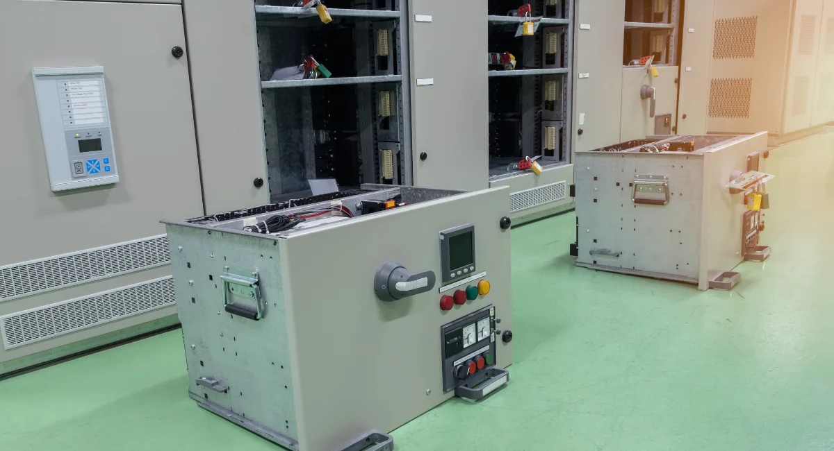
A motor control center (MCC) is a factory-made assembly of electrical devices that control the operation of typically three-phase motors. In the United States, MCCs are contained in sheet metal enclosures of modular design. MCCs can include fused and nonfused three-phase disconnects, control circuit transformers, motor starters, pilot control devices, and power monitoring/recording/management systems. Figure 1 shows a typical modular MCC. The modular nature of MCCs allows for many variations. While available in both low and medium voltage designs, most are of low voltage (600 VAC).

Figure 1 Motor Control Center
Primary Functions of Switchgear
MCCs, panelboards, load centers, and distribution boards facilitate the supply of the electrical power to the various loads within a facility. Many times this distribution is both to individual loads and smaller distribution boards, which in turn supply power to additional loads and/or to still smaller distribution boards.
The primary functions of electrical switchgear are to provide:
- Protection and coordination
- Isolation from energized parts
- Local and remote switching control
Switchgear Components
The following components are many times used to make up electrical switchgear:
- Fused and nonfused disconnects
- Contactors and motor starters
- PT and CT transformers
- Circuit breakers and fuses
- Power monitoring equipment
- Alarms
- Anticondensate cubical heaters
Additional devices such as control, energy monitoring, surge protection, and over/ under-voltage protective relays may also be provided.
Low-Voltage Power Distribution
Electrical power is typically routed to a single point. From this one point, power is distributed through the building. The following is a listing of the various distribution boards used in low-voltage power systems:
- Main switchboard
- Motor control center
- Sub distribution boards (panelboards)
- Final distribution boards (for lighting and power, called load centers)
The physical locations of the various types of switchgear vary with the nature of the facility. Some are near the main switchboard, while others may be near the loads served, with other distribution boards located throughout the facility.
Today most switchboards are built in a modular fashion. This allows for popular voltage, phase, and amperage sizes to be built as a type, and then various individual components selected and installed into the board as needed by the specific building. The various components can be one of three types, bolted units that cannot be isolated from the supply. These must be worked hot, or the power to the entire facility must be killed (placed in an electrically safe work condition).
An improvement from a safety point is the use of disconnectable types. With this type each individual unit is mounted on a module that can be removed from the board once the load has been turned off. This is made possible by the use of male and female separable connections between the individual bus bars and the module.
The final option is the use of drawer-type draw-out units that can be slid out of the board. Once the draw-out unit has been removed, it can be repaired or replaced. To improve safety, modern modular switchgear is built so that there are various isolating metal barriers between the supply bus bars, the individual modules, and between the modules and each other.
Bus Bar and Circuit Breaker Arrangements
NEMA switchgear has the breakers in a three-phase panel arranged in three vertical columns. Figure 2 shows the various arrangements of bus bars in MCCs. Each column connects the breakers in that column to one bus bar. The breakers are numbered from left to right, and from top to bottom.
- When the bus bars are arranged vertically, the first bar is connected to phase A. The next bar (center) is connected to phase B, and the third bus bar connects to phase C.
- When the bus bars are arranged horizontally, the top bus bar is phase A, the next lower bus bar is phase B, and the lowest bus bar is connected to phase C. The individual three-phase breakers connect to each of the three bus bars.

Figure 2 Three-Phase Bus Bars in Vertical Arrangement
When the panel is a single-phase model, the bus bars are typically arranged vertically. The first breaker is installed in the first slot on the left and connects to phase A. The first breaker on the top right connects to phase B. The first breaker is numbered one, on the top left, followed by two on the top right, the next lower breaker on the left is numbered three, and the next lower breaker on the right is numbered four. This results in all of the odd-numbered breakers being installed on the left, and all of the even-numbered breakers being installed on the right, in a top to bottom order.
Figure 3 shows a typical bus bar arrangement in an electrical panel.

Figure 3 Single-Phase Load Center Used as Service Equipment
NEMA panels have their main power lugs located at the top (when installed vertically) of the panel. Some panels are provided as main lugs only, while others have a main circuit breaker. When the panel has a main circuit breaker, it is installed at the top of the panel and connects to the bus bars.
While not common, it is possible to have a circuit breaker installed in a back feed position. When this is done, a breaker installed in a location typically used for a branch circuit breaker is used to feed power to the panel from the normal load terminals of the breaker. The NEC places restrictions on the use of back feed circuit breakers.
When panels are designed as service equipment, the neutral and ground bus bars are provided with a means of connecting the ground bus bar to the panel’s metal enclosure. This results in a single-phase distribution panel having two hot bus bars, a neutral bus bar, and an equipment grounding conductor bus bar.
For many years, NEMA standards allowed for a maximum of 42 circuits in a single panel. This restriction has now been removed. IEC consumer units (somewhat like a NEMA load center with miniature circuit breakers) may have between 6 and 24 breaker slots.
When the panel is used as service equipment, a means is provided to connect both the neutral and the ground bus bars together. Caution should be exercised when the panel is not used as a service panel. The ground and neutral bus bars must not be bonded together. That is, they must be electrically isolated from each other. The ground bus must be bonded to the enclosure in all cases. Many times this is done with a green-headed threaded machine screw.
Circuit Breakers
A circuit breaker is a special type of switchgear designed to be able to interrupt fault currents without damage to itself. Their construction allows them to interrupt fault currents of many hundreds or thousands of amps.
The methods used in quenching the arc falls into four types:
- Oil circuit breakers rely on vaporization of some of the oil to blast a jet of oil through the arc.
- Gas-insulated (SF6) circuit breakers sometimes stretch the arc using a magnetic field, and then rely on the dielectric strength of the insulating gas to quench the stretched arc.
- Vacuum circuit breakers have minimal arcing (as there is no gas to ionize), so the arc quenches when it is stretched a few thousandths of an inch. Vacuum circuit breakers are frequently used in medium voltage switchgear to 35 kV.
- Air circuit breakers (ACB) use either ambient or compressed air to extinguish the arc.
Circuit breakers are designed to terminate current flow between three to five cycles.
Optional Protective Devices
Besides the standard thermal-magnetic and magnetic only circuit breakers (MCP), there are many other protective devices that may be added to a lineup of switchgear. The following is a brief listing:
- Over- and/or under-voltage
- Phase sequence
- Thermal overload
- Instantaneous
- Phase loss
- Direction overcurrent
- Physical lock-out devices
- Differential protective relay
Metal-Clad Switchgear
Metal-clad switchgear is defined by ANSI/IEE C37.3202 as metal-enclosed power switchgear. This equipment has removable, draw-out-type switching and interrupting devices with connect and disconnect positions. The major parts of the switchgear are enclosed by metal barriers that are grounded for compartmentalization.
When the switchgear is removed, sometimes automatic shutters cover primary and secondary stabs. All primary bus conductors and connections are typically covered with insulation material. Exercise caution when working in switchgear as this insulation material is not intended to protect personnel from electrical shock.
Metal-Clad Switchgear Voltage Ratings
Some metal-clad switchgear manufacturers offer 38-kV-class switchgear with a 170-kV basic insulation level (BIL). SF-6 insulated (GIS) switchgear may have even higher BILs.
Continuous Current Ratings
Current ratings of bus bars in the metal-clad switchgear are 1,200 A; 2,000 A; and 3,000 A. Some manufacturers can supply 4,000 A continuously rated bus bars.
Breaker continuous current ratings are normally 1,200 A; 2,000 A; and 3,000 A for 15 kV class. Some manufacturers can increase these breaker ratings to as high as 4,000 A. This is accomplished by adding cooling fans to the breaker itself or by adding the cooling fans to the cell, allowing a standard 3,000 A breaker providing a total continuous breaker cell rating of 4,000 A. With 27 and 38 kV class, breaker ratings are 1,200 A and 2,000 A.
Arc-Resistant Switchgear
This class of product has gained popularity in North America over the past few years and in particular in Canada where it is said to have originated.
The applicable North American Standard used for testing is EEMAC (Electrical Equipment Manufacturers Association of Canada) G14–1 Procedure for Testing the Resistance of Metal-Clad Switchgear Under Conditions of Arcing Due to An Internal Fault.
In the last few years, a few manufacturers have been marketing “arc resistant” switchgear. This equipment provides an increased level of safety to personnel who may be in close proximity to the equipment should an arc fault condition develop within the switchgear.
Arc-resistant switchgear test criteria to the EEMAC standard includes:
- Properly secured doors, covers, and so forth, that do not open under tested arc fault conditions
- No hazard due to flying parts
- Arcing does not cause holes in sides of switchgear covers
- Flame test indicators
- Grounding connection remains effective
Arc-resistant switchgear is now certifiable by UL and UL-C (for Canada). Some metal-clad switchgear manufacturers have tested their arc-resistant switchgear to what some consider to be as rigorous IEC standards.
EEMAC-tested arc-resistant switchgear includes three basic types of accessibility:
- Accessibility Type A, which is arc-resistant construction at the front of the equipment only.
- Accessibility Type B, which is arc-resistant construction at the front, back, and sides of the equipment.
- Accessibility Type C, which is arc-resistant construction at the front, back, and sides and between compartments within the same cell or adjacent cells.
There is an exception to Type C allowed in which a fault in the bus bar compartment of a feeder cell is allowed to break into the bus bar compartment of an adjacent feeder. Some manufacturers have undertaken tests on metal-clad switchgear to preclude this from taking place and, instead, contain the arc within the bus compartment of any feeder cell.
Some overseas manufacturers offer switchgear with spring dampers that open to relieve the pressure during an arc blast fault.