Overcurrent protection devices (OCPD) can be either one-time use fuses or resettable circuit breakers. Circuit breakers come in the following types:
- Molded case circuit breakers
- Miniature circuit breakers
- Vacuum circuit breakers
- Insulated case circuit breakers
- Low-voltage power circuit breakers
- Supplemental protectors
- Motor circuit protectors
- Oil circuit breakers
- Gas-insulated circuit breakers
Figure 1 provides a typical diagram of the relationship between time and current for inverse time circuit breakers. The words inverse time are used to communicate that as the current increases, the time required for the circuit breaker to open decreases. Circuit breakers operate to protect the circuit from abnormal and potentially unsafe conditions.
Some circuit breakers have both a thermal and a magnetic sensing element. The thermal element responds to running overloads (percentage increases above rated current), while the magnetic element responds to short circuits (multiples of rated current).
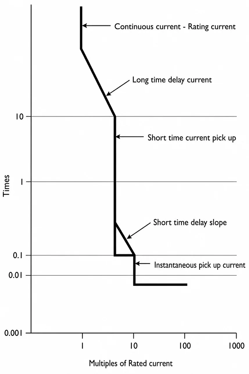
Figure 1 Thermal-Magnetic Circuit Breaker Inverse Time Current Curve
Inductive-type loads such as motors, when power is first applied, pull multiples of their rated current. This is normal; there is nothing wrong with the motor, so the OCPD should not open the circuit. If the motor was running and shorted out and started pulling, say, 300 amps, the OCPD should open the circuit immediately without delay under this short circuit condition. In the preceding, two different cases have been considered, one where the OCPD should act instantly, without delay, and another where it should delay, opening the protected circuit. As it takes time for the thermal element to heat up, it protects the circuit from running overloads. A magnetic field can build up instantly, so the magnetic element acts to protect the circuit without delay against short circuits.
Molded Case Circuit Breakers
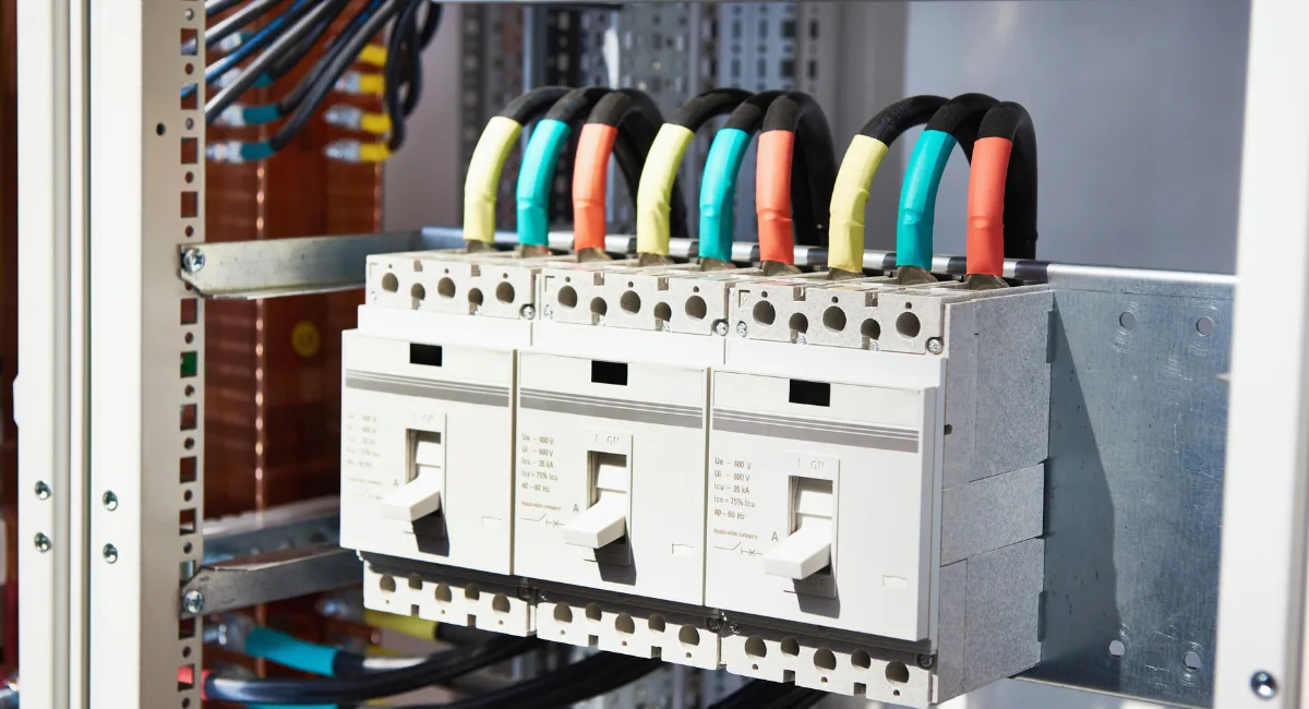
Molded case circuit breakers (MCCB) are by far the most commonly used breakers in residential, commercial, and industrial facilities. MCCBs have current ratings in standard increments between 15 and 6,000 A. Figure 2 is a drawing of a typical three-phase MCCB. Internally, they may have either a thermal or magnetic trip element, or they may have both types of trip elements.
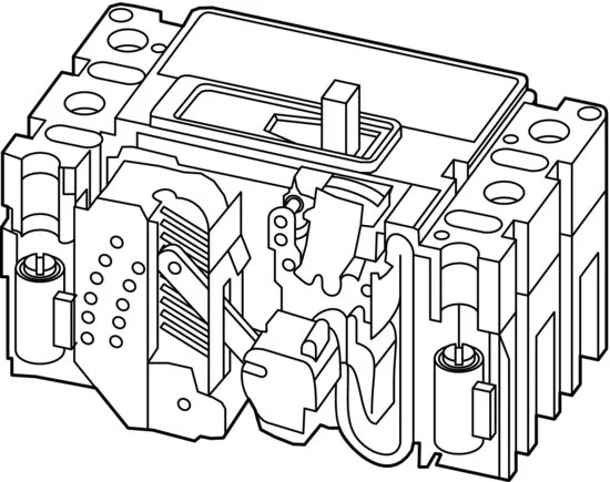
Figure 2 Three-Phase Molded Case Circuit Breaker
Both miniature and molded case circuit breakers have contacts exposed to ambient air. They are either electromechanically controlled or microprocessor controlled and are often used for main power distribution in small and medium-sized facilities and industrial plants.
An MCCB that has only a magnetic element is called a motor circuit protector (MCP). MCPs are used to provide short circuit protection, while a motor starter provides the running overload protection.
In low-voltage systems circuit breakers come in one-pole for 120 and 277 VAC, two-pole for 208, 240, or 480 VAC, and three-pole for 208, 240, and 480 VAC. When the neutral conductor must be opened, four pole breakers are used. Multipole breakers open all poles (switches) at the same time. A breaker must not be installed where its voltage rating will be exceeded. For example, a 120/240 slash-rated breaker should not be used to control a 277 V lighting circuit.
Circuit breakers also have an ampere rating. Breakers under about 200 amps are tested in free air. When they are placed in a metal box such as a load center or panelboard, they can carry continuously only 80 percent of their rating. Breakers rated above about 200 amps are 100 percent rated. Therefore, a 30-amp breaker can only carry 80 percent of its rating continuously.
80% of 30 is (.8 × 3) 24 amps
When the breaker is located in a much hotter location, say, in a poorly ventilated boiler room, the thermal element may trip the breaker sooner than it normally would. Where this occurs, an ambient compensated breaker should be considered for use.
The operating handle of a breaker can be in either the on or off position, or a little over the midpoint, which is the tripped position. MCCBs can be mounted by either some type of stab-lock, push-in/pull-out method, or bolted in place. Power must be removed before attempting to remove a breaker. With bolted breakers, check to see if the bolt is still hot, most likely it may be necessary to kill power to the entire panel before the bolt(s) can be removed.
Breakers with a thermal element exhibit an inverse current and time relationship. That is, as the amount of current flowing in the circuit increases, the sooner the breaker will open to protect the circuit component from overheating.
Breakers can be considered as being high temperature limit switches. When the temperature of the conductor and its electrical insulation increases, the breaker’s thermal element temperature increases, and when the point is reached that the insulation is in danger of being damaged, the breaker opens its contacts, stopping the current flow in the circuit. The size of an insulated electrical conductor is typically selected for 125 percent of the connected load. That is, breakers are sized to prevent the circuit from overheating.
As an example, for an appliance with a rated load of 16 amps, the circuit conductor would be rated at 20 amps, and the circuit breaker at 20 amps. Should the circuit begin to pull 20 amps for an extended time, the breaker’s thermal element would open the circuit. Should this same appliance short out internally and begin to pull short circuit amps of over 100 amps, the magnetic element would open the circuit without delay.
When a breaker trips out, the operating handle moves to a position about 60 percent of the way between the on and off positions. As a safety feature, when a breaker opens it means that something is wrong and should be corrected.
Miniature Circuit Breakers
Miniature circuit breakers (MCBs) typically have a rating of less than 200 A and have either thermal, or thermal and magnetic elements. Mounting options include flush, surface, or use of a 35 mm DIN rail. Connection options include lugs on both ends, bolt on, or plug in. Some are rated for switch duty (SWD).
Many are Heating, Air Conditioning, and Refrigeration (HACR)–rated and are also rated for use with high intensity discharge (HID) lighting. Miniature circuit breakers are used extensively in Europe in residential panelboards known as consumer units (CU), and in commercial distribution boards. MCBs should not be confused with a supplemental protector used extensively in the United States, as they physically look very much alike.
Voltage ratings include 120/240 VAC, 125 VDC, and 277 VAC.
Vacuum Circuit Breakers
Figure 3 shows the electrical contacts enclosed in a vacuum tight enclosure. Vacuum circuit breakers (VCBs) have contacts encased in a vacuum bottle. A vacuum is free of any gas (air) to support an electrical arc. The arcing column is made up of metal vapor and electrons coming from the switch contacts. A very small amount of contact material is vaporized and the arc develops in this metal atmosphere, which fills the space. When current flow decreases, these metal vapors condense on the electrodes and a metal screen.
Vacuum circuit breakers have current ratings of up to 3,000 A and 35 kV. Vacuum breakers have longer service lives than air circuit breakers. In the medium-voltage applications, they provide an increase in reliability and capacity over MCCBs and insulated case breakers. With contacts contained in an airtight chamber, there is no risk of explosion, fire, or external effects arising from the vacuum bottles during the breaking process. They have longer maintenance intervals than other types of breakers.
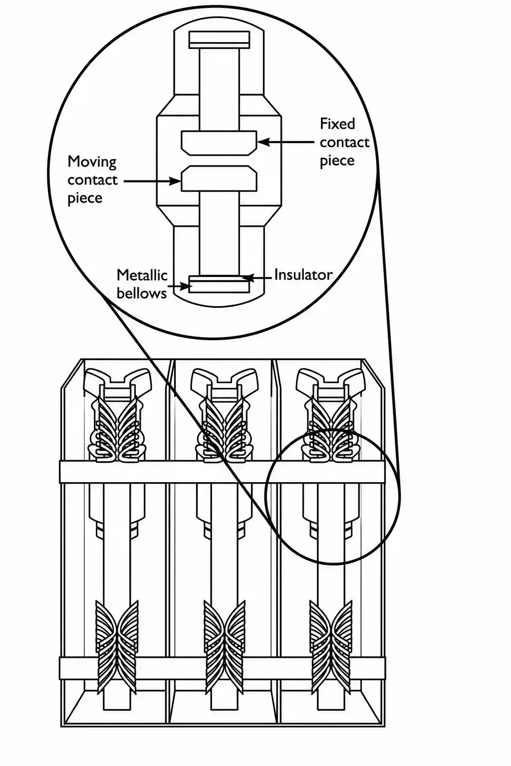
Figure 3 Three-Phase Vacuum Circuit Breaker
Insulated Case Circuit Breakers
Insulated case circuit breakers (ICCBs) are available in frame sizes from 400 to 5,000 A, with interrupting ratings of 65, 85, and 100 kAIC (thousand ampere interrupting capacity). Short time ratings of 25, 35, and 65 kA are available from several manufacturers. These breakers are rebuildable. They typically are made in a draw-out arrangement.
Low-Voltage Power Circuit Breakers
Low-voltage power circuit breakers (LVPCBs) are available in sizes ranging from 800 to 5,000 A, with interrupting ratings of 65, 85, and 100 kA at 600 V. Short time ratings of 35, 65, 85, and 100 kAIC are available.
Supplemental Protectors
Supplemental protectors devices (SPD) are molded case overcurrent devices listed for use within a machine to provide overcurrent protection for only the components located downstream of the SPD. While they physically look very like a MCCB, they are not allowed to provide branch circuit protection.
Motor Circuit Protectors
Motor Circuit Protector devices (MCPDs) are MCCBs with only a short circuit protecting element. While they physically look very much like a MCCB, they do not provide overload protection. They are used in conjunction with motor starters which provide the necessary running overload protection.
Oil Circuit Breakers
Oil circuit breakers have all but been eliminated from medium voltage applications due to the inherent fire danger. Oil circuit breakers are still in use in some large medium and high voltage applications, but are being replaced by vacuum circuit breakers and insulated gas (SF-6) circuit breakers.
Gas Insulated Circuit Breakers
A man made synthetic gas known as SF-6 is used in larger circuit breakers to provide an environment for high voltage and amperage contacts in medium and high voltage applications. SF-6 provides better electrical arc extinguishing abilities than both air and vacuum type circuit breakers. Virtually all high voltage circuit breakers in utility and industrial applications have their power contacts enclosed in a pressurized SF-6 electrical insulating gas environment.
Fuses
Fuses are commonly made using a lead alloy metal link enclosed within an environmentally sealed and electrically insulated tube. Their operation is dependent on the metal link melting to open the electrical circuit. Figure 4 shows both barrel and blade type fuses and the internal link.
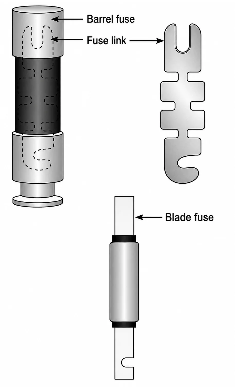
Figure 4 Electrical Fuse
Fuses are used frequently for circuit protection and work well, yet their design requires that they must be replaced every time they operate to clear an overcurrent condition.
Fuse element deterioration can occur due to environmental and physical stresses imposed by repeated short duration electrical overloads that do not cause the link to melt. As they are sealed in a nontransparent tube, maintenance personnel cannot determine this deteriorated condition. Fuses are very economical and available in a vast range of sizes in terms of voltage, amperage ratings, and interrupting ratings. They are a common type of circuit protective device used all around the world.
Fuse Operation
The operation of a fuse is as follows:
- The element heats up from ambient temperature when placed in operation. Its temperature increases further as current flow increases. The element heats up either slowly, due to a running overload condition over time, or it heats up instantly because of fault current flow.
- The element becomes plastic-like, and quickly melts, forming a gap in one or more places.
- An arc(s) is formed in one or more of the places along the element. As a plasma gas, the arc is extremely hot. This heat melts additional portions of the element, increasing the gap across the fuse link.
- As the arc is stretched, it becomes weaker and finally is unable to restrike when the zero voltage point is reached and the arc is extinguished.
- The circuit is isolated by the physical gap between the two ends of the fuse assembly housing.
It is standard practice in many critical applications that when a single fuse opens, all three fuses be replaced. Downtime typically exceeds the cost of replacing the other two fuses that still may be good. Open fuses should be taken apart and studied to determine what caused them to open. It may be of benefit to contact the fuse manufacturer for expert help on determining what caused the fuse to open.
Depending upon the construction of the fuse, it may be possible to determine if the cause was due to a running overload or short circuit by careful disassembly and inspection of the failed fuse.
Non-time-delay fuses can provide excellent short circuit protection. Non-time-delay fuses usually hold 500 percent of their rating for approximately one-fourth of one second after which the element melts. These fuses typically are not used in motor circuits which often have inrush currents in excess of five to eight times their rated load amps (RLA) or full load current (FLA).
Circuit Breaker Maintenance
MCCBs are contained within a case that is held together with rivets, so there are no components that can be field maintained in sizes up to about 200 amps. Breakers over the size of about 200 amps are designed so that they can be rebuilt. Insulated case, low, and medium voltage power circuit breakers (ICCB, LVPCB, and MVPCB, respectively), and vacuum circuit breakers (VCB) can be rebuilt.
All breakers should be inspected and tested periodically. Most manufacturers specify that a breaker be manually turned on and off about six times periodically. This aids in redistributing the lubricant inside of the breaker.
A noncontact infrared thermometer should be used to compare the temperature of the individual termination points to each other, and differences of three degrees or more should be investigated.
The voltage from phase to phase should also be checked on the load side of the breaker. Differences of 3 percent or more should be investigated.
Breakers can explode, just like a bomb! Before operating any breaker, the front panel cover must be fully secured in place before they are operated. To reduce the potential for injury, the “step to the side” method is recommended. Figure 5 shows the recommended step to the side position. It requires one to place a leather-gloved hand on the breaker’s operating handle, take a step to one side of the panel, and then operate the breaker.
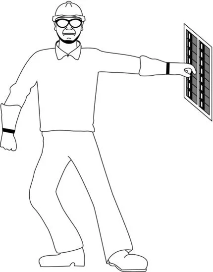
Figure 5 Safety Side Step
Should an extremely bad short circuit occur, the leather glove would provide some protection for the hand from being burned. By standing to the side, any flames, sparks, or missiles will not impact the face or torso.
Details as to the specific maintenance task for circuit breakers can be found in various standards produced by The International Electrical Testing Association (NETA) and the Recommended Equipment Maintenance Standard 70-B developed by the National Fire Protection Association (NFPA).
Coordination Between Protective Devices
When the various circuit protection devices are properly coordinated, only the smallest portion of the distribution system should experience an outage. Selective coordination is an engineering task. Maintenance and calibration of circuit breakers are maintenance tasks. Poor engineering or maintenance can result in a lack of coordination between overcurrent protective devices.